11
$\begingroup$

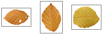
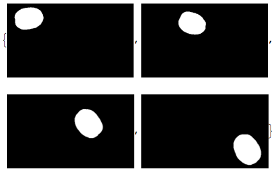
Given the PNG image below with the three leaves in it, I'd like to extract each individual leaf and write it to its own PNG file, using Mathematica 9. Note that in the original image, the box bounding a component may possibly intersect with another component, so that needs to be taken care of (i.e. each output PNG should have one complete leaf and no part of another leaf). The segmentation itself looks quite easy - just use the alpha channel, I'd say.

Hopefully this is a simple problem for an experienced Mathematica user (which I am not) - Mathematica just happens to be within reach and I figured it might be a good tool to use.

And if you could have the code go through a directory of images similar to this one, perform the desired operation on each PNG image in it and save the output images to another directory, that would be great! (the components of image.png should be saved as image1.png, image2.png, etc.)
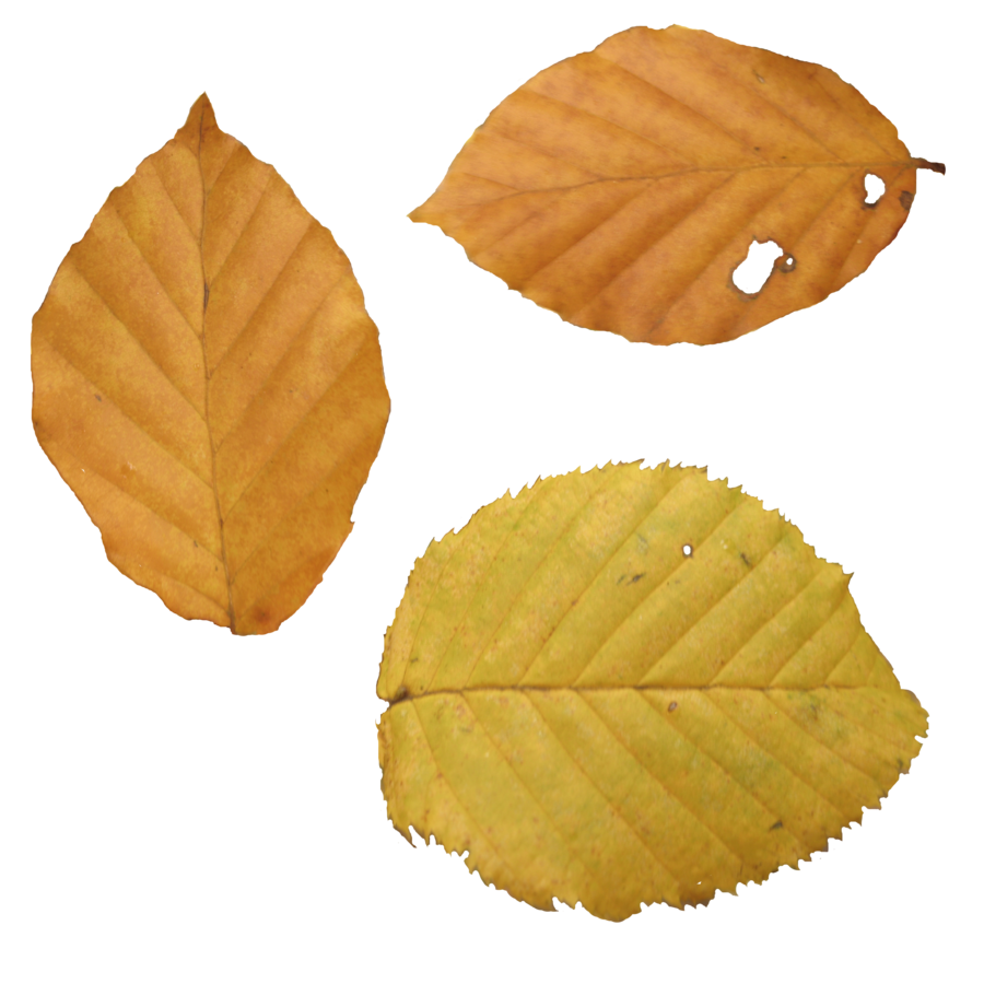
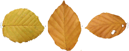
Edit: While it would obviously be unrealistic to expect a segmentation algorithm to work universally based on a single sample image that I showed, unfortunately some of the ones that have been suggested are failing for some cases they clearly shouldn't. Two examples below:
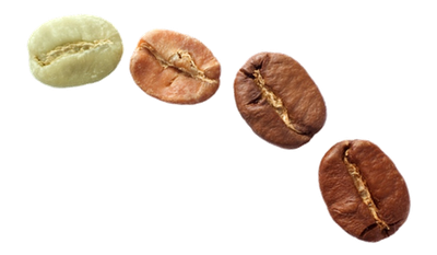
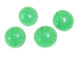
I'm hoping the authors will be able to modify their answers so that they work with these images (and hopefully most images "like" these ones), particularly if the problem is with the cropping/trimming/masking step (as opposed to the image preprocessing step, which might need to be "tuned" until it works for most examples).

I should mention that I am interested in the special case of PNG images where the AlphaChannel[] might be used to advantage, but I'm happy that the solutions offered so far are more generally applicable. I do need to be able to deal with cases in which the components are quite close together (but not touching).

$\endgroup$
2
  • 4
    $\begingroup$ Are you trying to learn Mathematica, or you just want this problem solved? If you are trying to learn, please write down the code you tried. Otherwise, if you just want the problem solved, go with any image processing application $\endgroup$ Commented Apr 1, 2013 at 15:25
  • $\begingroup$ @belisarius I just wanted the problem solved (although I would like to learn Mathematica properly, given the time). It seems an easy enough problem in general, and I thought it would be more convenient to do with Mathematica than with a (graphical) image processing application. Given that my approach with the question is earning disapproval, I guess I'll just dig into the documentation and see how far I get. $\endgroup$
    – Aky
    Commented Apr 1, 2013 at 15:40

3 Answers 3

20
$\begingroup$

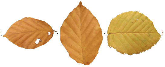
Edit Old answer follows below

The features of your new set are very different from the first image.
For example:

  • There are components "touching" the borders.

  • They have "hidden" structures like this:

    Mathematica graphics

So it needs a different approach:

l = {"https://i.sstatic.net/OZEvk.png", "https://i.sstatic.net/Tl1Pm.png", 
     "https://i.sstatic.net/8enYZ.png"};
i = Import /@ l;

mc = ComponentMeasurements[DeleteSmallComponents@FillingTransform@AlphaChannel@#,"Mask"]&/@i;
MapIndexed[ImageCrop@ImageMultiply[i[[#2[[1]]]], Image@#1] &, mc[[All, All, 2]], {2}]

Mathematica graphics

Old Answer:

Just to get you started:

i = Import@"https://i.sstatic.net/8enYZ.png"; 
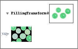
mc = Blur@FillingTransform@i~ ComponentMeasurements~ "Mask";
ImageCrop /@ (i~ ImageMultiply~ # & /@ Image /@ mc[[All, 2]])

Mathematica graphics

$\endgroup$
5
  • $\begingroup$ Brilliant, thanks! I was along the lines of MorphologicalComponents // DeleteSmallComponents and thinking I might apply some rules (->) to convert all but one component to 0 (background) and then ImageCrop, etc. but meanwhile you pretty much solved it! Mathematica is definitely a package/language I want to learn! $\endgroup$
    – Aky
    Commented Apr 1, 2013 at 15:54
  • 1
    $\begingroup$ @Aky I improved it a little. Mathematica isn't very easy to learn but is very powerful. You won't regret learning it $\endgroup$ Commented Apr 1, 2013 at 16:01
  • $\begingroup$ Could you check your implementation against two additional images I've linked in the question? $\endgroup$
    – Aky
    Commented Apr 2, 2013 at 10:10
  • $\begingroup$ @Aky Done, but in general image processing algorithms need a large sample set to ensure predictability. You can't expect to extrapolate the results from 3 images to a large database. $\endgroup$ Commented Apr 2, 2013 at 13:24
  • $\begingroup$ Thanks, much appreciated. I hadn't known about the hidden structures. I actually have enough experience with image processing (mostly using MATLAB though) to have known better, so sorry about that. The problem for me right now is using mma effectively rather than the conceptual aspects of image processing. So it all comes down to learning mma (which I've started doing) if I want to use it as a tool, and not to rely on mma SE for ready-baked solutions! $\endgroup$
    – Aky
    Commented Apr 2, 2013 at 14:38
14
$\begingroup$

Edit: Shorter ImageTrim version as pointed out by Matthias Odisio

Use MorphologicalComponents and utilize ComponentMeasures to extract the "BoundingBox" which is already the row- and column-number you can then feed directly to ImageTake or even better to ImageTrim. ImageTrim has the big advantage that it can handle the bounding box coordinates directly:

img = Import@"https://i.sstatic.net/8enYZ.png";

(* ImageTrim version *)
ImageTrim[img, #2] & @@@ ComponentMeasurements[
  MorphologicalComponents[Binarize[GaussianFilter[img, 3]]], "BoundingBox"]

Mathematica graphics

The GaussianFilter just smooths the image a bit to ensure that Binarize gives all 3 big objects with a bit of space around them.

The same result can be obtained using ImageTake but there is a disadvantage: A call to ImageReflect and some reverse and transposing is necessary because ImageTake works on image matrix coordinates while ComponentMeasures gives you a reversed but more natural coordinate system. Think of it as follows: if you take the 1st image matrix row you get the top row because this comes first but if you think of the usual Cartesian system, the y=1 would be at the bottom of the image.

ImageTake[img, Sequence @@ Reverse[Transpose[#2]]] & @@@ 
 ComponentMeasurements[MorphologicalComponents[
   Binarize[GaussianFilter[ImageReflect@img, 3]]], "BoundingBox"]
$\endgroup$
5
  • $\begingroup$ Thanks for your reply too. MorphologicalComponents was actually the first thing I looked at; it was more the question of putting together a solution the Mathematica way, which you and belisarius have shown two ways of doing. $\endgroup$
    – Aky
    Commented Apr 1, 2013 at 16:20
  • 1
    $\begingroup$ With the standard image coordinate system, it's better to use ImageTrim: ImageTrim[img, #[[2]]] & /@ ComponentMeasurements[MorphologicalComponents[Binarize[GaussianFilter[img, 3]]],"BoundingBox"] $\endgroup$ Commented Apr 1, 2013 at 21:56
  • $\begingroup$ @MatthiasOdisio I should have remembered this one because I was just last week talking to a colleague about this. It seems I'm too used to it due to the low level C/Java programming. Thanks. $\endgroup$
    – halirutan
    Commented Apr 1, 2013 at 22:22
  • $\begingroup$ Could you check your implementation against the image i.sstatic.net/Tl1Pm.png ? The fact that the components bounding boxes are intersecting (I think) are causing a problem. $\endgroup$
    – Aky
    Commented Apr 2, 2013 at 10:09
  • $\begingroup$ Please look up the help of ComponentMeasurements because there you find everything you need. Of course you run into trouble when the rectangular bounding box overlaps with another object but you could just use the "Mask" to mask this out: i.sstatic.net/77UKV.png $\endgroup$
    – halirutan
    Commented Apr 2, 2013 at 10:43
5
$\begingroup$

The two excellent answers to this question are from Mathematica experts who have trained rigorously for years at secret mountain-top monasteries, on a tungsten-enriched diet, to achieve these levels of effortless mastery. It can be hard for some of the rest of us to unravel their elegant phrasing...

I was working along these lines before I had to stop. There's definitely some room for improvement!

i = Import@"https://i.sstatic.net/8enYZ.png"; 
b = Dilation[Binarize[FillingTransform[GradientFilter[i, 2]]] , 5]

binarized

ifc = MorphologicalComponents[b];
cm = First /@ ComponentMeasurements[b, "Area"] /. Rule -> List

{1,2,3}

masks = ImageAdjust[Image[#]] & /@ (ifc /. x_ /; x != # -> 0  & /@ cm)

masks

ImageCrop[ImageMultiply[i,#]]  & /@ masks

final

Edit:

This particular code doesn't work so well if the objects are close together - the generous Dilation value I used fuses together some of the objects you've bravely added to your question. If you have hundreds of these, you'd have to find a value that worked well for all of them.

another image

$\endgroup$
6
  • 1
    $\begingroup$ Good step-by-step solution, thanks! More readable for a beginner like me. $\endgroup$
    – Aky
    Commented Apr 2, 2013 at 9:08
  • $\begingroup$ The dilation step is a bit problematic for images in which the components are quite close, because it can cause two separate components to join together. (But since the segmentation problem is fairly simple for the type of examples I'm interested in, I should be able to find a sequence of steps that can segment most of them.) $\endgroup$
    – Aky
    Commented Apr 2, 2013 at 10:29
  • $\begingroup$ My tungsten diet taught me that you may use cm = Range@Max@ifc $\endgroup$ Commented Apr 2, 2013 at 14:01
  • $\begingroup$ and also masks = Image /@ ((1 - Unitize[# - ifc]) & /@ cm) $\endgroup$ Commented Apr 2, 2013 at 14:05
  • $\begingroup$ @belisarius Thanks! I realise that if I learn 3 new Mathematica functions every day, I'll still be at it in 4 years' time... :) $\endgroup$
    – cormullion
    Commented Apr 2, 2013 at 14:16

Your Answer

By clicking “Post Your Answer”, you agree to our terms of service and acknowledge you have read our privacy policy.

Not the answer you're looking for? Browse other questions tagged or ask your own question.