3
$\begingroup$

From the question "How to get a list of vertices in a convex hull" I can get the list of vertices of each triangle that form each face of the convex hull from a set of {x,y,z} points and also close the triangles by adding the first vertice of each list of vertices at the end of that list.

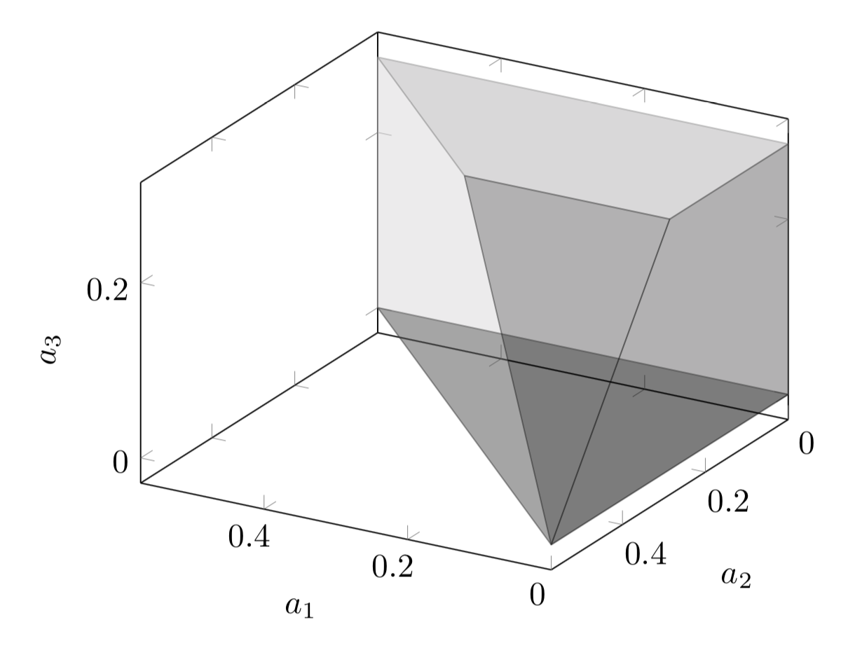
I am using these lists to plot the figures in $\LaTeX$ using Tikz. The problem with having triangles is that Tikz deals with each triangle as a different face or side of the convex hull and thus it shades them differently even if the triangles are in the same plane or face. For example, the closed triangles of the points in the above-referenced question are

{
{0, 4, 7, 0}, {7, 8, 1, 7}, {6, 4, 2, 6},
{4, 0, 2, 4}, {8, 7, 6, 8}, {7, 4, 6, 7},
{0, 1, 2, 0}, {0, 7, 1, 0}, {1, 8, 2, 1},
{8, 6, 2, 8}
}

which in Tikz plots as

enter image description here

and the results are confusing.

However, if I give the closed list of vertices contained in each face, excluding the connection lines on the same face,

{
 {8, 7, 0, 1, 8}, 
 {7, 8, 6, 4, 7},
 {4, 2, 1, 0, 4},
 {6, 8, 1, 2, 6},
 {4, 6, 2, 4, 4},
 {4, 7, 0, 4, 4}
}

then the output is clearer.

(The faces that are triangles must be closed twice since the lists of vertices must have the same length)

How could I get only the list of the vertices of each side without the edges on the same face of the convex hull?

enter image description here

$\endgroup$

2 Answers 2

9
$\begingroup$

We can use an internal function that merges adjacent coplanar faces and colinear lines.

Your data:

X = {
    {0,0,0},{0,0,0.285957},{0,0.285957,0.285957},{0,0.381238,0.190619},
    {0,0.571914,0},{0.190676,0.381238,0.190619},{0.285957,0.285957,0.285957},
    {0.571914,0,0},{0.571914,0,0.285957}
};

mesh = ConvexHullMesh[X];

Merge coplanar faces:

merged = Region`Mesh`MergeCells[mesh];

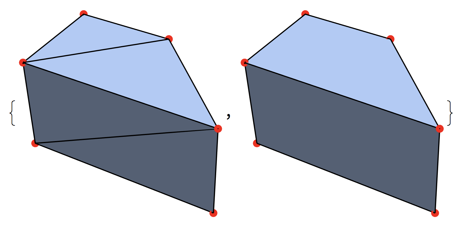
Compare the two meshes:

BoundaryMeshRegion[#, 
  MeshCellStyle -> {0 -> {PointSize[Large], Red}, 1 -> {Black, Thick}}
] & /@ {mesh, merged}

enter image description here

Obtain the cells and pad when necessary:

PadRight[{##}, 4, #1]& @@@ MeshCells[merged, 2][[All, 1]]
{{1, 4, 6, 1}, {5, 4, 3, 5}, {1, 6, 7, 2}, {4, 5, 7, 6}, {1, 2, 3, 4}, {2, 7, 5, 3}}
$\endgroup$
6
$\begingroup$

Here is one approach for 3D meshes:

  1. Group the faces by their normals.
  2. For each group, remove the edges that are shared between polygons.
  3. The vertices of the remaining edges from the new polygons
  4. Remove any vertices that are adjacent to only two faces.

The following function carries out this idea:

DetriangulateMesh[mesh_] := Module[{res = iDetriangulateMesh[mesh]},
    res /; RegionQ[res]
]

iDetriangulateMesh[mesh_] := Module[{dim, m1, v, e, fl, normals, pf, extra},
    Which[
        !RegionQ[mesh],
        Message[DetriagulateMesh::reg, mesh]; Return[$Failed],

        dim = RegionDimension[mesh];
        dim =!= 3, 
        Message[
            DetriangulateMesh::rnimpl,
            DetriangulateMesh,
            "dimension "<>ToString[dim]
        ];
        Return[$Failed]
    ];
    normals = Values @ GroupBy[
        Thread @ {
            Range @ MeshCellCount[mesh,2],
            standardize @ Region`Mesh`MeshCellNormals[mesh,2]
        },
        Last->First
    ];
    e = MeshCells[mesh, 1];
    v = MeshCoordinates[mesh];
    toedges = removePattern@mesh["ConnectivityMatrix"[2,1]];
    m1 = MeshRegion[
        v,
        Flatten[polys @* (e[[#]]&) @* singleEdges @* (toedges[[#]]&) /@ normals]
    ];
    pf = removePattern@m1["ConnectivityMatrix"[0,2]];
    extra = Pick[Range@Length@#, #, 2]& @ Total[pf,{2}];
    MeshRegion[
        MeshCoordinates[m1],
        MeshCells[m1, 2] /. Alternatives@@extra -> Sequence[]
    ]
]

standardize[data_] := With[{d = DeleteDuplicates @ Chop @ data},
    d[[Min /@ Nearest[d->"Index", data, {All, 10^-10}]]]
]

removePattern[s_SparseArray] := Normal[s] /. Verbatim[_] -> 1

singleEdges[m_] := With[{t = Total[m]},
    Pick[Range@Length @ t, t, 1]
]

polys[lines_] := Module[
    {edges = lines /. Line[{a__}] :> UndirectedEdge[a], cc},

    cc = Subgraph[edges,#]& /@ ConnectedComponents[edges];
    toPolygon /@ cc
]

toPolygon[g_] := With[{e = First @ EdgeList[g], v = VertexList[g]},
    Polygon @ First @ FindPath[g, Sequence@@e, {Length[v]-1}]
]

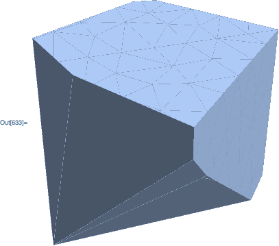
An example:

SeedRandom[1]
mesh = RegionIntersection[
    ConvexHullMesh[RandomReal[2, {10,3}]],
    DiscretizeRegion@HalfSpace[{-1,0,0},{.1,.1,.1}]
]

enter image description here

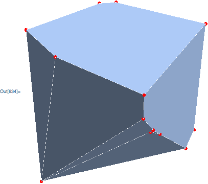
The mesh after detriangulation, with the remaining vertices highlighted in red:

HighlightMesh[
    DetriangulateMesh[mesh],
    {Style[0,{PointSize[Large],Red}], Style[1, White]}
]

enter image description here

For the example in the linked question:

X = {
    {0,0,0},{0,0,0.285957},{0,0.285957,0.285957},{0,0.381238,0.190619},
    {0,0.571914,0},{0.190676,0.381238,0.190619},{0.285957,0.285957,0.285957},
    {0.571914,0,0},{0.571914,0,0.285957}
};

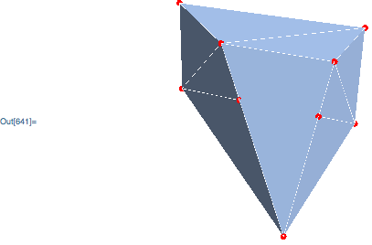
mesh = ConvexHullMesh[X];

Highlight the vertices and edges:

HighlightMesh[
    mesh,
    {Style[0, {PointSize[Large],Red}], Style[1, White]},
    ViewPoint->{-1, 2, 1}
]

enter image description here

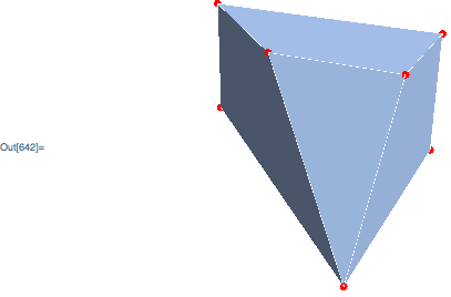
Use DetriangulateMesh:

HighlightMesh[
    DetriangulateMesh[mesh],
    {Style[0, {PointSize[Large],Red}], Style[1, White]},
    ViewPoint->{-1, 2, 1}
]

enter image description here

$\endgroup$

Your Answer

By clicking “Post Your Answer”, you agree to our terms of service and acknowledge you have read our privacy policy.

Not the answer you're looking for? Browse other questions tagged or ask your own question.