10
$\begingroup$

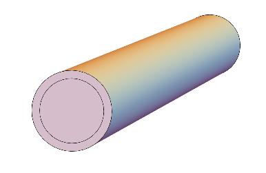
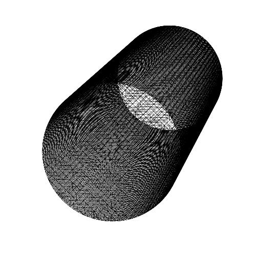
I'm trying to follow the documentation for Element Mesh Generation, but somehow I cannot understand it correctly. Here is a simplified version of my real problem. I'm trying to simulate the temperature distribution in a pipeline. In the pipeline, there should be a fluid (fluid flow) and a solid domain (pipe wall). These 2 domains have different equations and should be connected with each other with NeumannValue.

E.g. I'd like to have something like this

pipe

wall[x_, y_, z_] := ((0.9/10)^2 <= x^2 + y^2 <= 0.1^2) && 0 <= z <= 1
fluid[x_,y_,z_] := x^2 + y^2 < (0.9/10)^2 && 0 <= z <= 1

RegionUnion doesn't give me what I want, because the internal boundary would disappear. Does anyone have an idea?

EDIT:

here is something I tried

  1. I thought to build a solid region and a fluid region, retrieve their boundary elements and coordinates and use ToBoundaryMesh could work, but it didn't.

000

\[CapitalOmega]1 = ImplicitRegion[wall[x, y, z], {x, y, z}];

With[{mesh = ToElementMesh[\[CapitalOmega]1]},co1 = mesh["Coordinates"]; be1 = mesh["BoundaryElements"];]

\[CapitalOmega]2 = ImplicitRegion[fluid[x, y, z], {x, y, z}];

With[{mesh = ToElementMesh[\[CapitalOmega]2]},
co2 = mesh["Coordinates"];
be2 = mesh["BoundaryElements"];]

bmesh = ToBoundaryMesh["Coordinates" -> Join[co1, co2], "BoundaryElements" -> Join[be1, be2]]

ToBoundaryMesh::fememib: The input has or generated an intersecting boundary and cannot be processed.
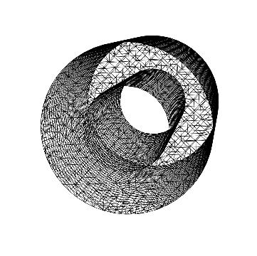
  1. I thought I could treat the fluid domain as a RegionHole, but it also didn't work. mesh

Obviously, it only contains the pipe wall not the fluid.

bmesh = ToBoundaryMesh[ImplicitRegion[wall[x, y, z], {x, y, z}]]
ToElementMesh[bmesh, "RegionHoles" -> None]["Wireframe"]

Update

@user21's solution somehow fails in the other situations. E.g.

L = 0.5; 
hi = 2/3 1.25; 
ri = 0.01; 
m = ToElementMesh[
      ImplicitRegion[-L/2 <= x <= L/2 && 
        0 <= y <= 1.25 && ! (x^2 + (y - hi)^2 < ri^2), {x, y}], 
      "RegionHoles" -> None(*,"RegionMarker"\[Rule]{{{0,hi},1,10},{{0,
      1.25/3},2,0.1}},*), "MeshOrder" -> 1, MaxCellMeasure -> Infinity]
m["Wireframe"]
coords = m["Coordinates"];
c1 = Join[coords, ConstantArray[{0.}, {Length[coords]}], 2];
c2 = Join[coords, ConstantArray[{1.}, {Length[coords]}], 2];
ele = m["MeshElements"];
max = Max[ElementIncidents[ele]]
tohigherIndex[type_[inci_, marker___], max_] := 
 type[inci + max, marker]
tmpBM = ToBoundaryMesh[m];
sides = QuadElement[Map[Join[#1, Reverse[#1 + max]] &, #]] & /@ 
   ElementIncidents[
    Flatten[MeshElementSplitByMarker[tmpBM["BoundaryElements"]]]];
bm = ToBoundaryMesh["Coordinates" -> Join[c1, c2], 
  "BoundaryElements" -> 
   Join[ele, tohigherIndex[#, max] & /@ ele, sides]]
bm["Wireframe"]

The code above gives me the following error

TriangleElement::femdmi: Mesh element type TriangleElement does not match incidents {}.
ToBoundaryMesh::fembdel: TriangleElement[{{60,96,95},{19,95,96},{60,59,9},{95,59,60},{19,11,635},{1182,10,67},{10,1182,11},{1182,67,79},{95,635,79},{635,95,19},{79,635,1182},{1182,635,11}}] is not a valid mesh element. Possible causes are that the mesh element type is not valid, not enough coordinates have been specified, or that incidents have values less than or equal to zero.

Is there any solution that can be generalized to random geometry?

$\endgroup$
2
  • $\begingroup$ Please show the code you have tried. $\endgroup$
    – bbgodfrey
    Commented May 3, 2018 at 20:27
  • $\begingroup$ @bbgodfrey I added the code $\endgroup$
    – 407PZ
    Commented May 3, 2018 at 20:43

3 Answers 3

5
$\begingroup$

Update: I have updated the code a bit to work in other cases as well.

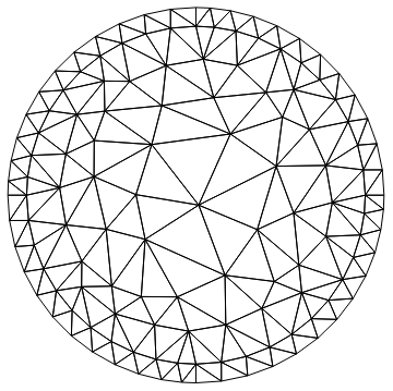
Yes, this is too difficult. Here is a workaround for this case. It's not trivial but it works well for the problem at hand. Basically, we generate a boundary mesh from a 2D mesh that has an interior region:

m = ToElementMesh[Annulus[{0, 0}, {9/10, 1}], "RegionHoles" -> None, 
   "MeshOrder" -> 1, MaxCellMeasure -> Infinity];
m["Wireframe"]

enter image description here

Next, we extract the coordinates and get the largest incident number.

coords = m["Coordinates"];
c1 = Join[coords, ConstantArray[{0.}, {Length[coords]}], 2];
c2 = Join[coords, ConstantArray[{1.}, {Length[coords]}], 2];
ele = m["MeshElements"];
max = Max[ElementIncidents[ele]]
136

We extract the boundary elements from the mesh and construct the sides:

tohigherIndex[type_[inci_, marker___], max_] := 
 type[inci + max, marker]
(* old code: not good *)
(* tmpBM = ToBoundaryMesh[m];
sides = QuadElement[Map[Join[#1, Reverse[#1 + max]] &, #]] & /@ 
   ElementIncidents[
    Flatten[MeshElementSplitByMarker[tmpBM["BoundaryElements"]]]];*)
sides = QuadElement[Map[Join[#1, Reverse[#1 + max]] &, #]] & /@ 
   ElementIncidents[
    Flatten[MeshElementSplitByMarker[m["BoundaryElements"]]]];

We now construct the boundary mesh:

bm = ToBoundaryMesh["Coordinates" -> Join[c1, c2], 
  "BoundaryElements" -> 
   Join[ele, tohigherIndex[#, max] & /@ ele, sides]]

bm["Wireframe"]

enter image description here

And generate the full mesh:

ToElementMesh[bm]["Wireframe"]

enter image description here

Hope this helps.

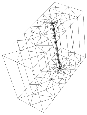
With the updated version I get this for your second mesh:

enter image description here

$\endgroup$
3
  • $\begingroup$ Is it possible to generalize the procedure? I'm encountering a similar situation now and your technique doesn't work any more. $\endgroup$
    – 407PZ
    Commented Jul 25, 2018 at 11:08
  • $\begingroup$ @407Peezy Try the updated code and see if that works for you. $\endgroup$
    – user21
    Commented Jul 25, 2018 at 14:21
  • $\begingroup$ Thanks! It works like a charm! $\endgroup$
    – 407PZ
    Commented Jul 25, 2018 at 15:52
11
$\begingroup$

Maybe it helps to have different "RegionMarker" for different domains? I am not sure if this is useful for OP original problem regarding boundary conditions, but I would like to show another approach to generating such FEM mesh.

Since the geometry of this pipe is quite simple we can mesh it with structured quadrilaterals. This also gives you a lot more control over element size and distribution. I have been developing a package MeshTools to help with this.

Load the package after installing it and define geometry parameters.

Needs["MeshTools`"]
center = {0, 0};
r1 = 0.9; (* inner radius *)
r2 = 1.; (* outer radius *)
n = 10; (* number of elements on quarter of disk perimeter *)
length = 4; (* length of cylinder *)
n2 = 10; (* number of elements in length direction *)

Create structured mesh on Disk. This represents the "fluid" domain.

diskMesh = DiskMesh[center, r1, n]
(* ElementMesh[{{-0.9, 0.9}, {-0.9, 0.9}}, QuadElement["<" 220 ">"]}] *)

Create structured mesh on Annulus, which represents the "solid" domain. Element spacing on the edge should match the one of diskMesh.

annulusMesh = AnnulusMesh[center, {r1, r2}, {4*n, 2}]
(* ElementMesh[{{-1., 1.}, {-1., 1.}}, {QuadElement["<" 80 ">"]}] *)

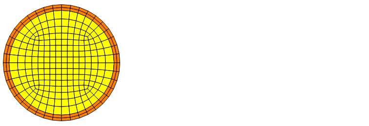
Observe the result for both meshes (they are still two different ElementMesh objects).

Show[
  diskMesh["Wireframe"["MeshElementStyle" -> FaceForm@Yellow]],
  annulusMesh["Wireframe"["MeshElementStyle" -> FaceForm@Orange]]
]

mesh2D

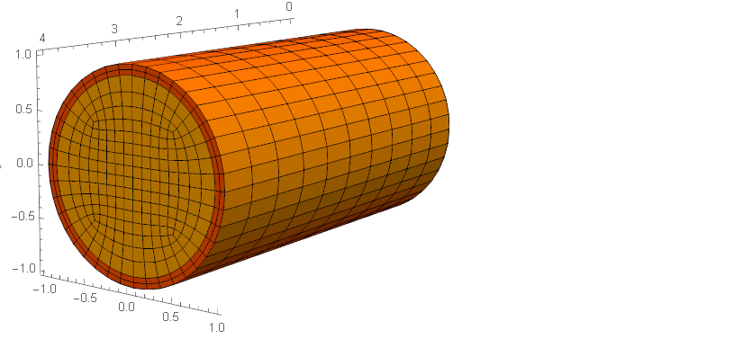
And then the crucial step. Extrude quadrialteral meshes in Z direction, add "RegionMarker" of your choice and merge meshes into one ElementMesh object.

mesh3D = MergeMesh[{
   AddMeshMarkers[ExtrudeMesh[diskMesh, length, n2],"MeshElementsMarker" -> 1],
   AddMeshMarkers[ExtrudeMesh[annulusMesh, length, n2],"MeshElementsMarker" -> 2]
}]

mesh3D["Wireframe"[
  "MeshElement" -> "MeshElements",
  "MeshElementStyle" -> FaceForm /@ {Yellow, Orange},
  Axes -> True
]]

mesh3D

$\endgroup$
6
$\begingroup$

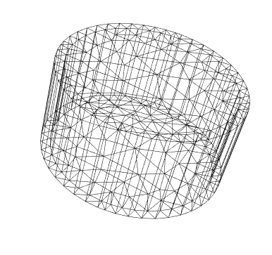
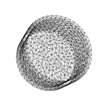
I managed to find a dirty solution on my own. If the fluid part is removed completely like what I did in the second try, Mathematica will not consider it as a RegionHole. Thus, the idea is not to remove it completely. Somehow this dirty solution works with the equations too.

wholeRegion[x_, y_, z_] := (x^2 + y^2 <= 0.1^2) && 0 <= z <= 1
fluid[x_,y_,z_] := x^2 + y^2 < (0.9/10)^2 && 0.01 <= z <= 0.99
bmesh = ToBoundaryMesh[
  ImplicitRegion[wholeRegion[x, y, z] && ! fluid[x, y, z], {x, y, z}],
   "RegionHoles" -> {0, 0, 0.5}, 
  "MaxBoundaryCellMeasure" -> 10^(-4)]
mesh = ToElementMesh[bmesh, "RegionHoles" -> None(*,
  MaxCellMeasure\[Rule]10^-5*)]

enter image description here

But still, I hope that Wolfram could optimize the RegionHole to make generating the 3D internal subregion easier.

$\endgroup$

Your Answer

By clicking “Post Your Answer”, you agree to our terms of service and acknowledge you have read our privacy policy.

Not the answer you're looking for? Browse other questions tagged or ask your own question.