Version 1
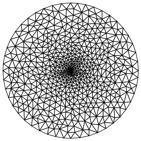
One way to do it could be to generate a 2D disk mesh with an appropriate refinement and the extrude that to 3D.
(m2 = ToElementMesh[Disk[{0, 0}, 0.003],
    MeshRefinementFunction ->
     Function[{vertices, area},
      area > 0.00000005 (0.001 +
          500 Norm[Mean[vertices]])]])["Wireframe"]
mesh = ElementMeshRegionProduct[m2,
  ToElementMesh[Line[{{0}, {0.01}}]]]


mesh["Wireframe"]

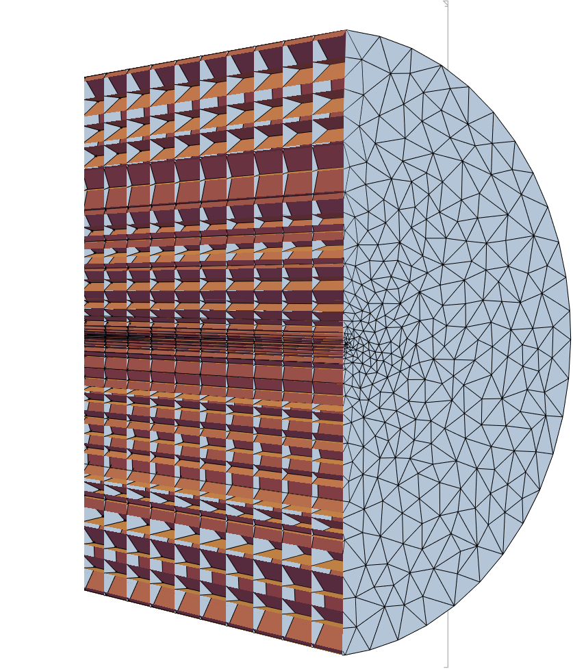
Here is a view inside:
mesh["Wireframe"["MeshElement" -> "MeshElements",
  "ElementMeshDirective" ->
   Directive[EdgeForm[Black], FaceForm[LightGray]],
  PlotRange -> {{-0.003, 0}, All, {0, 0.005}}]]
Version 2
A variant of this approach is to use a graded mesh for the element mesh region product, like so:
m1 = ToGradedMesh[{Line[{{0}, {0.01}}], <|
     "Alignment" -> "BothEnds"|>}];
MeshRegion[m1]

mesh = ElementMeshRegionProduct[m2, m1];

mesh["Wireframe"["MeshElement" -> "MeshElements",
  "ElementMeshDirective" ->
   Directive[EdgeForm[Black], FaceForm[LightGray]],
  PlotRange -> {{-0.003, 0}, All, {0, 0.005}}]]
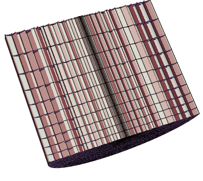
Note, how the mesh is becoming denser towards the bottom (and top not shown) Here is a view of the boundaries:
mesh["Wireframe"[
  "MeshElementStyle" -> {FaceForm[Green], FaceForm[Red],
    FaceForm[Blue]}, PlotRange -> {{-0.003, 0}, All, {0, 0.01}}]]

Version 3
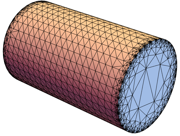
Here is a version that has a refined boundary but a coarse interior:
Needs["NDSolve`FEM`"]
c1 = Cylinder[{{0, 0, 0}, {0.01, 0, 0}}, 0.003];
mesh = ToElementMesh[c1, "MaxBoundaryCellMeasure" -> 0.1,
   "MaxCellMeasure" -> Infinity];
Show[mesh["Wireframe"], Graphics3D[c1]]
Cross section:
mesh["Wireframe"["MeshElement" -> "MeshElements",
  "ElementMeshDirective" ->
   Directive[EdgeForm[Black], FaceForm[LightGray]],
  PlotRange -> {{0, 0.005}, {0, 0.003}, {0, 0.003}}]]

Version 4
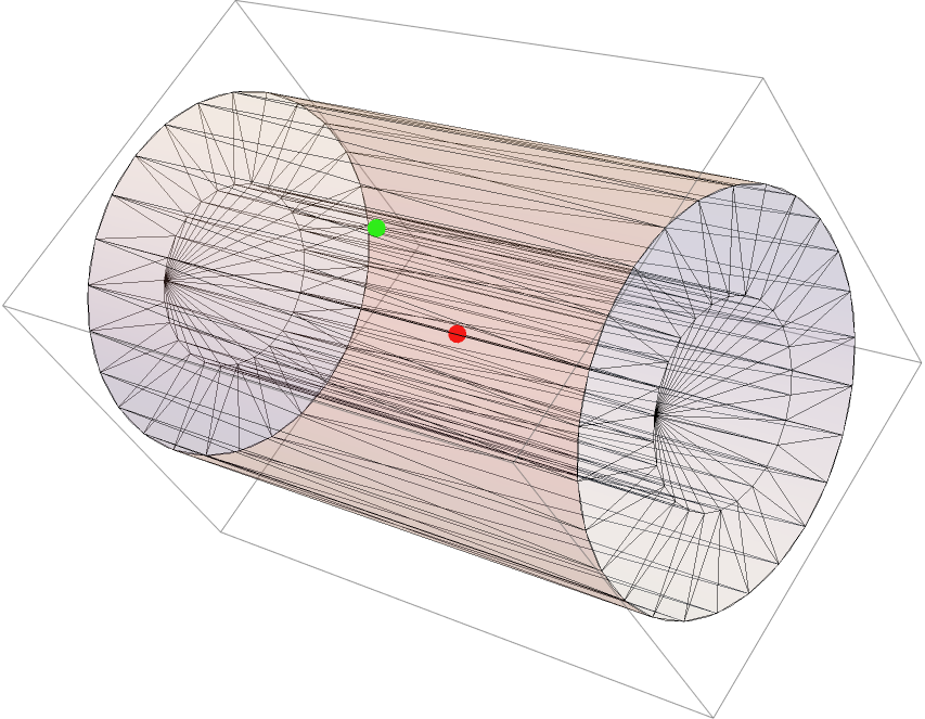
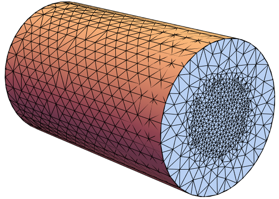
Yet another way to do it would be by using OpenCascade and create an inner cylinder that is refined to a different level.
Needs["NDSolve`FEM`"]
Needs["OpenCascadeLink`"]
c1 = Cylinder[{{0, 0, 0}, {0.01, 0, 0}}, 0.003];
c2 = Cylinder[{{0, 0, 0}, {0.01, 0, 0}}, 0.003/2];

s1 = OpenCascadeShape[c1];
s2 = OpenCascadeShape[c2];

faces = Flatten[OpenCascadeShapeFaces /@ {s1, s2}];
union = OpenCascadeShapeUnion[faces];

bmesh = OpenCascadeShapeSurfaceMeshToBoundaryMesh[union];

bmesh["Wireframe"]

Create to material markers p1 and p2:
p1 = {0.01/2, 0, 0};
p2 = {0.01/2, 0, 0.005/2};
Show[
 Graphics3D[{{Red, PointSize[0.02], Point[p1]}, {Green,
    PointSize[0.02], Point[p2]}}],
 bmesh["Wireframe"],
 Graphics3D[{Opacity[0.2], c1}]]
mesh = ToElementMesh[bmesh,
   "RegionMarker" -> {{p1, 1, 10^-12}, {p2, 2, 10^-10}}];
Show[mesh["Wireframe"], Graphics3D[c1]]
Version 5
Here is a version with a MeshRefinementFunction. By testing I found that the mesh changes when a "MaxCellMeasure" around 10^-11 was given. So I create a function that re-scales around this value from 0 to the boundary at 0.003.
Needs["NDSolve`FEM`"]
rescale = Rescale[Sqrt[y^2 + z^2], {0, 0.003}, {10^-14, 10^-11}]
The Sqrt[y^2 + z^2] is just the radial distance from the x-axis. This I then injected into the mesh refinement function:
c1 = Cylinder[{{0, 0, 0}, {0.01, 0, 0}}, 0.003];
cf = With[{r = rescale},
   Compile[{{coordinates, _Real, 2}, {vol, _Real, 0}},
    Block[{com, x, y, z, rvol},
     com = Mean[coordinates];
     {x, y, z} = com;
     rvol = r;
     If[vol > rvol, True, False]
     ]
    ]
   ];
mesh = ToElementMesh[c1, MeshRefinementFunction -> cf]
Show[mesh["Wireframe"], Graphics3D[c1]]


MeshRefinementFunction. Perhaps start by searching the site with that keyword. $\endgroup$