1
$\begingroup$

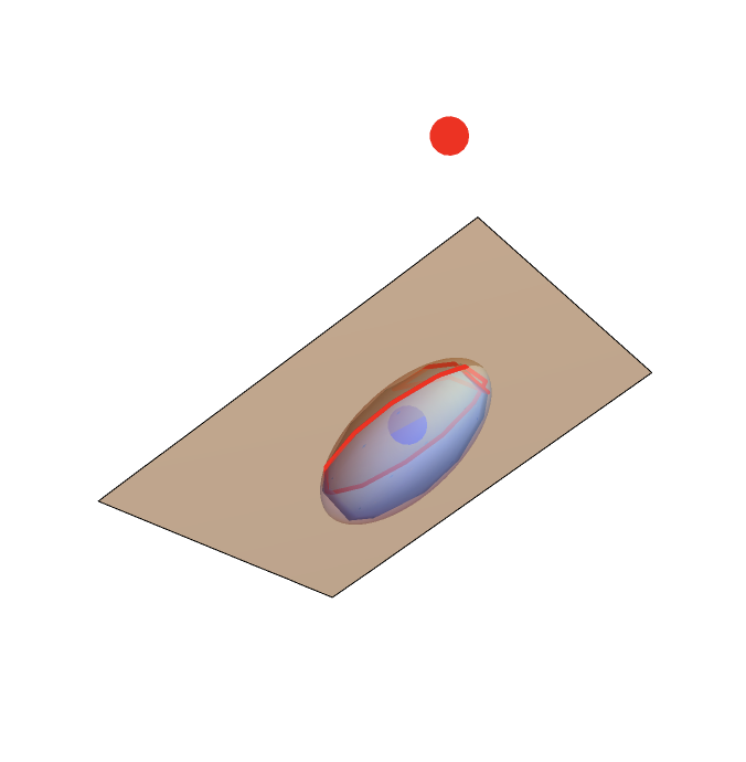
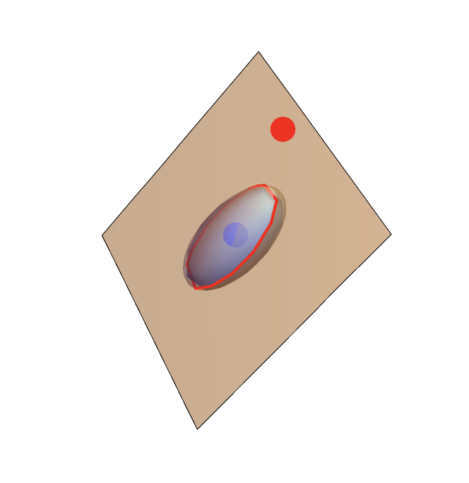
I am working on writing a code to find the polar plane of an ellipse, and subsequently calculate the cap formed by subtending the point $p$ (red) onto a random ellipse.

I think I have managed to compute the polar plane/ellipse of intersection using the algorithm referenced here (https://hal.science/hal-01402302v3/document), though there are some plotting issues potentially, and now I would like to compute the surface area of the ellipsoidal cap on the side closest to the red point (blue point shows the translation of the ellipsoid into coordinate system with the ellipsoid at the origin)

Here is my code so far:

ClearAll[crossProduct, frisvadOrthoBasis, EllipsoidToEllipse]

crossProduct[a_, b_] := {
   a[[2]]*b[[3]] - a[[3]]*b[[2]],
   a[[3]]*b[[1]] - a[[1]]*b[[3]],
   a[[1]]*b[[2]] - a[[2]]*b[[1]]
   };

frisvadOrthoBasis[v0_] := Module[{v = v0},
  (*Normalize input vector*)
  v = Normalize[v];
  (*First orthonormal basis vector*)
  u1 = v;
  (*Second orthonormal basis vector*)
  If[
   Abs[u1[[1]]] > Abs[u1[[2]]],
   u2 = {-u1[[3]], 0, u1[[1]]};,
   u2 = {0, u1[[3]], -u1[[2]]};
   ];
  u2 = Normalize[u2];
  (*Third orthonormal basis vector*)
  u3 = Cross[u1, u2];
  (*Return the orthonormal basis vectors*)
  Return[{u2, u3}];
  ]

EllipsoidToEllipse[A10_, A20_, A30_, a10_, a20_, a30_, Pa0_] := 
 Module[{
   A1 = A10, A2 = A20, A3 = A30, a1 = a10, a2 = a20, a3 = a30, Pa = Pa0
   },
  
  
  (*This function assumes that the ellipsoid lies with its centroid \
at the origin*)
  
  (*3.1 ellipsoid to sphere*)
  M = Transpose[Join[{A1, A2, A3}]] . DiagonalMatrix[{a1, a2, a3}] . 
    Join[{A1, A2, A3}];
  (*Print["M",M];*)
  Minv = Inverse[M];
  Pb = Minv . Pa;
  (*3.2 sphere to disk*)
  theta = ArcSin[1/Norm[Pb]];
  (*Print["theta ",theta];*)
  Pc = (Cos[theta]^2)*Pb;
  (*Print["Pc ",Pc];*)
  radius = Tan[theta]*Norm[Pc];
  (*Print["radius ",radius];*)
  {C1, C2} = frisvadOrthoBasis[Pc/Norm[Pc]];
  (*3.3 disk to ellipse*)
  (*Print["C1 ", C1];*)
  (*Print["C2 ", C2];*)
  Pd = M . Pc;
  D1 = M . (radius*C1);
  (*Print["D1 first",D1];*)
  D2 = M . (radius*C2);
  (*Print["D2 first",D2];*)
  (*3.4 ellipse principal axes*)
  Q = {{Dot[D1, D1], Dot[D1, D2]}, {Dot[D1, D2], Dot[D2, D2]}};
  {eigenvalues, eigenvectors} = Eigensystem[Q];
  (*Print[eigenvectors];*)
  D1 = eigenvectors[[1, 1]]*D1 + eigenvectors[[2, 1]]*D2;
  (*Print["D1 before",D1];*)
  D1 /= Norm[D1];
  (*Print["D1 after",D1];*)
  D2 = eigenvectors[[1, 2]]*D1 + eigenvectors[[2, 2]]*D2;
  (*Print[D2];*)
  D2 /= Norm[D2];
  (*Print["Eigenvalues",eigenvalues];*)
  {d1, d2} = Sqrt[eigenvalues];
  Return[{Pd, D1, D2, d1, d2}];]

Manipulate[
 Show[
  
  Graphics3D[{
    {Red, PointSize[0.05], Point[{px, py, pz}]},
    {Opacity[0.5], Ellipsoid[{0, 0, 0}, {a1, a2, a3}]
     },


    (*Lets plot the point of the plane*)
    {Blue, PointSize[0.05], 
     Point[EllipsoidToEllipse[{1, 0, 0}, {0, 1, 0}, {0, 0, 1}, a1, a2,
          a3, {-px, -py, -pz}][[1]] + {px, py, pz}]},
    
    
    }, Boxed -> False],


  {
   ContourPlot3D[
    
    {
     Cross[
        Evaluate[(*EllipsoidToEllipse[{1,0,0},{0,1,0},{0,0,1},a1,a2,
         a3,{-px,-py,-pz}][[1]] +{px,py,
         pz}+*)(EllipsoidToEllipse[{1, 0, 0}, {0, 1, 0}, {0, 0, 1}, 
              a1, a2, a3, {-px, -py, -pz}][[3]]*
            
            EllipsoidToEllipse[{1, 0, 0}, {0, 1, 0}, {0, 0, 1}, a1, 
              a2, a3, {-px, -py, -pz}][[
             5]]) - (EllipsoidToEllipse[{1, 0, 0}, {0, 1, 0}, {0, 0, 
               1}, a1, a2, a3, {-px, -py, -pz}][[1]] + {px, py, pz}) ],
        
        Evaluate[(*EllipsoidToEllipse[{1,0,0},{0,1,0},{0,0,1},a1,a2,
         a3,{-px,-py,-pz}][[1]] +{px,py,
         pz}+*)(EllipsoidToEllipse[{1, 0, 0}, {0, 1, 0}, {0, 0, 1}, 
              a1, a2, a3, {-px, -py, -pz}][[2]]*
            
            EllipsoidToEllipse[{1, 0, 0}, {0, 1, 0}, {0, 0, 1}, a1, 
              a2, a3, {-px, -py, -pz}][[4]])
          
          - (EllipsoidToEllipse[{1, 0, 0}, {0, 1, 0}, {0, 0, 1}, a1, 
              a2, a3, {-px, -py, -pz}][[1]] + {px, py, pz})]
        ] . ({x, y, 
          z} - (EllipsoidToEllipse[{1, 0, 0}, {0, 1, 0}, {0, 0, 1}, 
             a1, a2, a3, {-px, -py, -pz}][[1]] + {px, py, pz})) == 0,
     
     
     (x/a1)^2 + (y/a2)^2 + (z/a3)^2 - 1 == 0
     
     }, {x, -0.5, 0.5}, {y, -0.5, 0.5}, {z, -0.6, 0.6}, 
    ContourStyle -> Opacity[0.5]
    
    , MeshFunctions -> Function[
      (*Start of Mesh Intersection contour*)
      {x, y, z},
      (*Start of Mesh Intersection function*)
      Cross[
         
         Evaluate[(*EllipsoidToEllipse[{1,0,0},{0,1,0},{0,0,1},a1,a2,
          a3,{-px,-py,-pz}][[1]] +{px,py,
          pz}+*)(EllipsoidToEllipse[{1, 0, 0}, {0, 1, 0}, {0, 0, 1}, 
               a1, a2, a3, {-px, -py, -pz}][[3]]*
             
             EllipsoidToEllipse[{1, 0, 0}, {0, 1, 0}, {0, 0, 1}, a1, 
               a2, a3, {-px, -py, -pz}][[
              5]]) - (EllipsoidToEllipse[{1, 0, 0}, {0, 1, 0}, {0, 0, 
                1}, a1, a2, a3, {-px, -py, -pz}][[1]] + {px, py, 
              pz}) ],
         
         
         Evaluate[(*EllipsoidToEllipse[{1,0,0},{0,1,0},{0,0,1},a1,a2,
          a3,{-px,-py,-pz}][[1]] +{px,py,
          pz}+*)(EllipsoidToEllipse[{1, 0, 0}, {0, 1, 0}, {0, 0, 1}, 
               a1, a2, a3, {-px, -py, -pz}][[2]]*
             
             EllipsoidToEllipse[{1, 0, 0}, {0, 1, 0}, {0, 0, 1}, a1, 
               a2, a3, {-px, -py, -pz}][[4]])
           
           - (EllipsoidToEllipse[{1, 0, 0}, {0, 1, 0}, {0, 0, 1}, a1, 
               a2, a3, {-px, -py, -pz}][[1]] + {px, py, pz})]
         ] . ({x, y, 
           z} - (EllipsoidToEllipse[{1, 0, 0}, {0, 1, 0}, {0, 0, 1}, 
              a1, a2, a3, {-px, -py, -pz}][[1]] + {px, py, pz}))
       
       - ((x/a1)^2 + (y/a2)^2 + (z/a3)^2 - 1)
      
      (*End of Mesh Intersection function*)
      ]
    , MeshStyle -> {Thick, Red}, Mesh -> {{0}}
    ]}


  ]


 ,
 {px, -1, 1},
 {py, -1, 1},
 {pz, -1, 1},
 {{a1, 0.15}, 0.1, 1},
 {{a2, 0.15}, 0.1, 1},
 {{a3, 0.3}, 0.1, 1}
 ]

Thanks for your help and assistance!

Red contour is supposed to be the polar plane/ellipse of intersection subtended by the red point onto the ellipse

enter image description here

$\endgroup$
5
  • $\begingroup$ What is the polar plane? How to define polar plane? $\endgroup$
    – cvgmt
    Commented May 1 at 1:14
  • $\begingroup$ Let $p$ be at the origin $p=(0,0,0)$ and let $E$ be an ellipsoid that has centroid at Pa, with orthonormal triaxial vectors (ie major/minor axis vectors) $A1$ $A2$ and $A3$ defining the principle axes of the ellipsoid, with the major/minor axes lengths being $a1$, $a2$ and $a3$. $\endgroup$
    – MKF
    Commented May 1 at 4:49
  • $\begingroup$ Then define a line $l$ from $p=(0,0,0)$ to $T_q E$ where $q$ lies along the surface of ellipsoid $E$ where $l$ is a line inside the tangent plane at the point $q$ on $E$ $\endgroup$
    – MKF
    Commented May 1 at 4:51
  • $\begingroup$ The set of all of the tangent planes form a set of such $q$ for all the possible tangent planes which lie on $E$ and extend a line to $p$ $\endgroup$
    – MKF
    Commented May 1 at 4:53
  • $\begingroup$ But this set of $q$ naturally form an ellipse on the surface of $E$, and this ellipse must lie in a plane on the surface of $E$. This plane is the so called polar plane of an ellipsoid subtended by the point $p$ $\endgroup$
    – MKF
    Commented May 1 at 4:54

1 Answer 1

4
$\begingroup$
  • For the ellipsoid equation $$\frac{(x-\text{p1})^2}{\text{a1}^2}+\frac{(y-\text{p2})^2}{\text{a2}^2}+\frac{(z-\text{p3})^2}{\text{a3}^2}=1$$ and a point (pole ) {o1,o2,o3}, it's polar plane just has the form

$$\frac{(\text{o1}-\text{p1}) (x-\text{p1})}{\text{a1}^2}+\frac{(\text{o2}-\text{p2}) (y-\text{p2})}{\text{a2}^2}+\frac{(\text{o3}-\text{p3}) (z-\text{p3})}{\text{a3}^2}=1$$

The main reasion is that the the normal vector of the tangent plane of such ellipsoid is

Clear["Global`*"];
f[x_, y_,z_] := (x - p1)^2/a1^2 + (y - p2)^2/a2^2 + (z - p3)^2/a3^2 - 1;
Grad[f[x, y, z], {x, y, z}]

$$\left\{\frac{2 (x-\text{p1})}{\text{a1}^2},\frac{2 (y-\text{p2})}{\text{a2}^2},\frac{2 (z-\text{p3})}{\text{a3}^2}\right\}$$

and the direction of the tangent lines is orthogonal to such normal vector.

  • We can use Mathematica to prove the polar equation.
Clear["Global`*"];
center = {p1, p2, p3};
axes = {a1, a2, a3};
pole = {o1, o2, o3};
f[x_, y_, 
   z_] := (x - p1)^2/a1^2 + (y - p2)^2/a2^2 + (z - p3)^2/a3^2 - 1;
tangent = 
  1/2 (Grad[f[x, y, z], {x, y, z}] . ({X, Y, Z} - {x, y, z}) /. {X -> 
        o1, Y -> o2, Z -> o3}) == 0;
surface = f[x, y, z] == 0;
AddSides[tangent, surface] // Simplify

enter image description here

Clear["Global`*"];
center = {p1, p2, p3} = {0.2, .4, .8};
axes = {a1, a2, a3} = {.8, .4, .5};
pole = {o1, o2, o3} = {0, 0, 0};
f[x_, y_, 
   z_] := (x - p1)^2/a1^2 + (y - p2)^2/a2^2 + (z - p3)^2/a3^2 - 1;
polar[x_, y_, 
   z_] := ((x - p1)  (o1 - p1))/a1^2 + ((y - p2)  (o2 - p2))/
    a2^2 + ((z - p3)  (o3 - p3))/a3^2 - 1;
ellipsoid = 
  ContourPlot3D[
   f[x, y, z] == 0 // Evaluate, {x, p1 - a1, p1 + a1}, {y, p2 - a2, 
    p2 + a2}, {z, p3 - a3, p3 + a3}, 
   MeshFunctions -> Function[{x, y, z}, polar[x, y, z]], 
   Mesh -> {{0}}, 
   MeshShading -> {Directive@{Opacity[.5], Green}, 
     Directive@{Opacity[.5], Blue}}, 
   MeshStyle -> Directive@{Thick, Yellow}, BoxRatios -> Automatic, 
   Boxed -> False, Axes -> False];
polarplane = 
  ContourPlot3D[
   polar[x, y, z] == 0 // Evaluate, {x, p1 - a1, p1 + a1}, {y, 
    p2 - a2, p2 + a2}, {z, p3 - a3, p3 + a3}, Mesh -> None];
point = Graphics3D[{Red, AbsolutePointSize[5], Point@{o1, o2, o3}}];
pts = MeshPrimitives[
    DiscretizeRegion[
     ImplicitRegion[{f[x, y, z] == 0, polar[x, y, z] == 0}, {x, y, 
       z}]], 1][[;; , 1]][[;; , 1]]; index = 
 FindShortestTour@pts // Last;
cone = Graphics3D[{EdgeForm[], FaceForm[Yellow], Opacity[.8], 
    Polygon /@ (Join[{{o1, o2, o3}}, #] & /@ 
       Partition[pts[[index]], 2, 1])}];
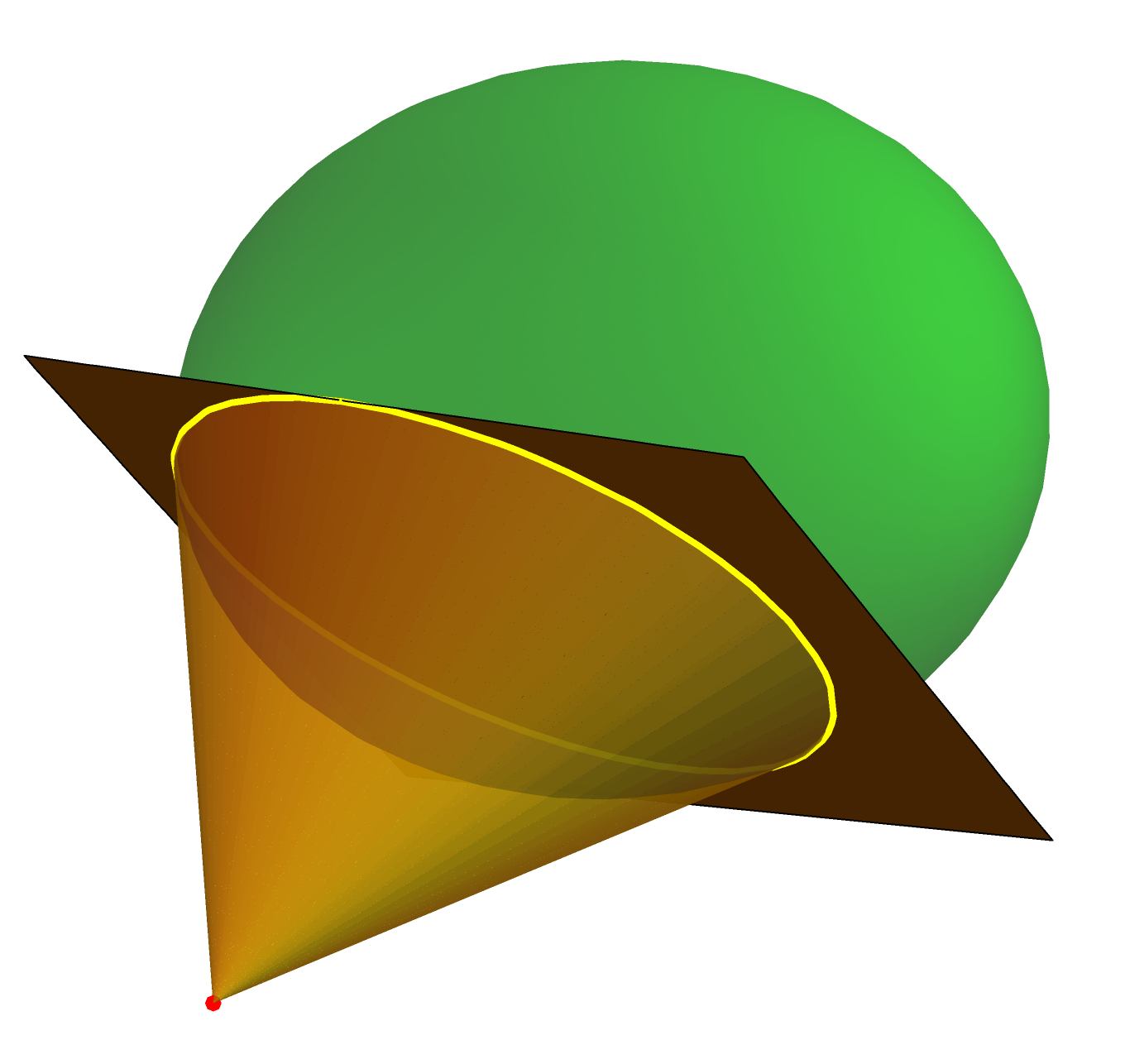
Show[ellipsoid, polarplane, point, cone, PlotRange -> All]

enter image description here

and the areas of the two parts (blue and green) are

area1 = ImplicitRegion[{f[x, y, z] == 0, polar[x, y, z] >= 0}, {x, y, 
     z}] // Area;
area2 = ImplicitRegion[{f[x, y, z] == 0, polar[x, y, z] <= 0}, {x, y, 
     z}] // Area;
{area1, area2}

{0.970791, 2.96791}

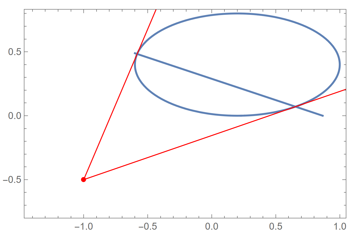
  • Such method also work for the 2D cases. In the 2D cases is just the polar of the quadratic curves.
Clear["Global`*"];
center = {p1, p2} = {0.2, .4};
axes = {a1, a2} = {.8, .4};
pole = {o1, o2} = {-1, -.5};
f[x_, y_] := (x - p1)^2/a1^2 + (y - p2)^2/a2^2 - 1;
polar[x_, 
   y_] := ((x - p1)   (o1 - p1))/a1^2 + ((y - p2)   (o2 - p2))/a2^2 - 
   1;
ellipsoid = 
  ContourPlot[
   f[x, y] == 0 // Evaluate, {x, p1 - a1, p1 + a1}, {y, p2 - a2, 
    p2 + a2}, MeshFunctions -> Function[{x, y}, polar[x, y]], 
   Mesh -> {{0}}, AspectRatio -> Automatic, Axes -> False];
polarline = 
  ContourPlot[
   polar[x, y] == 0 // Evaluate, {x, p1 - a1, p1 + a1}, {y, p2 - a2, 
    p2 + a2}, Mesh -> None];
pts = {x, y} /. NSolve[{f[x, y] == 0, polar[x, y] == 0}, {x, y}];
g = Graphics[{Red, AbsolutePointSize[5], Point@{o1, o2}, 
    HalfLine[{{o1, o2}, pts[[1]]}], HalfLine[{{o1, o2}, pts[[2]]}]}];
Show[ellipsoid, polarline, g, PlotRange -> All]
length1 = 
  ImplicitRegion[{f[x, y] == 0, polar[x, y] >= 0}, {x, y}] // 
   ArcLength;
length2 = 
  ImplicitRegion[{f[x, y] == 0, polar[x, y] <= 0}, {x, y}] // 
   ArcLength;
{length1, length2}

enter image description here

{1.51619, 2.35919}

$\endgroup$
2
  • $\begingroup$ We can also draw the infinite cone. cone = Graphics3D[{EdgeForm[], FaceForm[{Opacity[.8], Yellow}], ConicHullRegion[{{o1, o2, o3}}, #] & /@ Partition[pts[[index]], 2, 1]}, PlotRange -> All] $\endgroup$
    – cvgmt
    Commented May 2 at 10:01
  • $\begingroup$ Wow, this is fantastic! thanks so much @cvgmt! $\endgroup$
    – MKF
    Commented May 7 at 0:33

Your Answer

By clicking “Post Your Answer”, you agree to our terms of service and acknowledge you have read our privacy policy.