This answer is based on the initial solution by @dinesh (OP) and suggestions (very much on point) from @C. E. and @Domen.
The short version.
Input: OP's provided image.
Output:
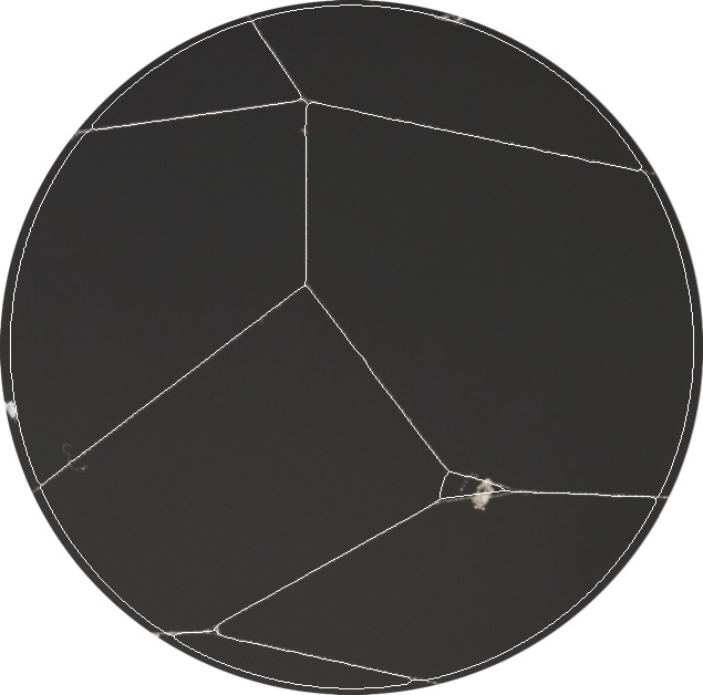
Before explaining, I would like to note the main issues:
- The uppermost and the lowermost web thread vertices are slightly
distorted
- Some of the field of view is lost
- The two above issues mean that there are possible non-negligible (up to the OP) errors in the web gap areas
- Based on only one image it is hard to say how robust/automatable this is
Might be able to fix these in the future, unless someone else beats me to it. For now, here is how the solution works.
It seemed from the OP's attempt that the object in the smaller gap might be a problem, so it should be removed. First one needs a mask:
inpaintMask = Dilation[#, DiskMatrix@3] &@Closing[#, DiskMatrix@5] &@(
  DeleteSmallComponents[#, 15] &@Binarize@# -
   ColorNegate@FillingTransform@Binarize@ColorNegate@#
  ) &@webInput;

ImageAdd[
 webInput,
 ColorReplace[#, White -> Yellow] &@EdgeDetect@inpaintMask
 ]
where webInput is the OP's image; DeleteSmallComponents[#, 15] &@Binarize@# detects the artefact and -ColorNegate@FillingTransform@Binarize@ColorNegate@# excludes the segments at the circular field of view boundary.
Dilation "bloats" the mask to better remove the artefact with inpainting:
webClean = Inpaint[
  webInput, inpaintMask,
  Method -> {"TextureSynthesis", "MaxSamples" -> 500, "NeighborCount" -> 50}
  ]
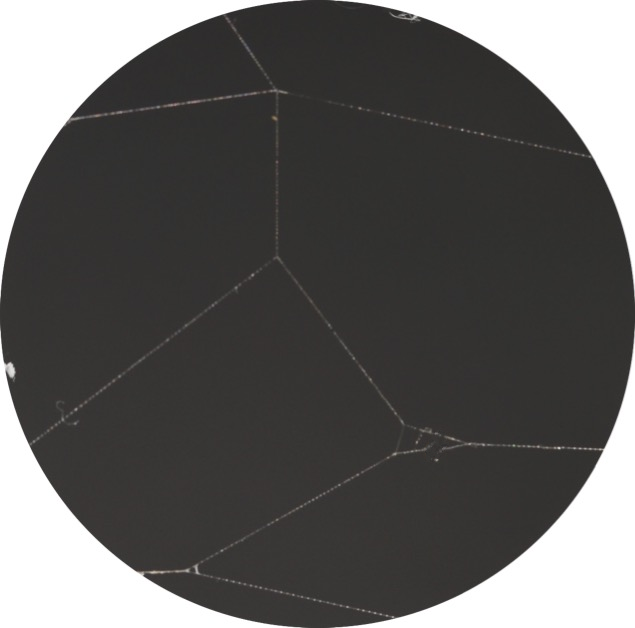
which thankfully correctly fills in the upper web thread, but alas deforms the lower thread.
Now use the OP's initial solution:
webTopHat = ImageAdjust@TopHatTransform[#, 2] &@webClean
which by the way can be visualized more clearly with 2*webTopHat. Now the threads with breaks in them can be repaired and binarized. Taking the suggestion of @C. E. but replacing dilation with Gaussian filtering before binarizing as suggested by @Domen
webBinarized = LocalAdaptiveBinarize[#, 15] &@
    ImageAdjust@GaussianFilter[#, 2] &@webTopHat
one has this:
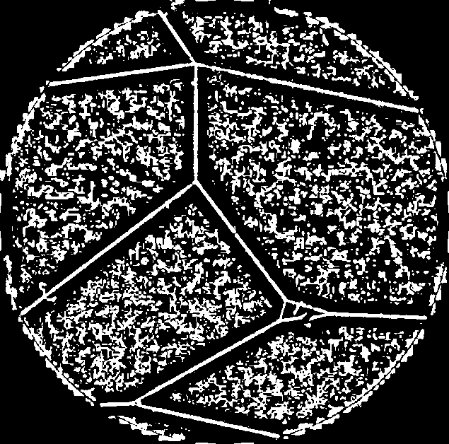
where one has two problems: the artefacts in the web gaps and at the circular boundary. Note that applying this step without top-hat transforming the input produces coarser artefacts which are a lot harder (may not be possible in other OP's images) to get rid of. Also, the artefact that was removed previously interferes with binarization rather badly and corrupts the smaller web gap.
To remove the interior/boundary artefacts, one first needs a mask of the circular field of view. Not knowing if the other OP's images contain any boundary artefacts, the circular mask is found as follows:
circleMaskEstimate =
 ImagePad[#, -10, Black] &@FillingTransform@Closing[#, 3] &@
    ImagePad[#, 10, Black] &@ColorNegate@Binarize@webClean


circleMaskEstimateContracted =
 ImagePad[#, -10, Black] &@Erosion[#, DiskMatrix@6] &@
    ImagePad[#, 10, Black] &@circleMaskEstimate
where ImagePad (removed after operations) prevents boundary artefacts and the contracted mask circleMaskEstimateContracted will be used a bit later on. As a safeguard from boundary artefacts in the source images, this estimate is refined by fitting a circle:
    whitePixels =
      PixelValuePositions[EdgeDetect@circleMaskEstimateContracted, 1];

    fitError =
      Total[Map[Function[whitePixel, (Norm[{cx, cy} - whitePixel] - r)^2],
         whitePixels]];

    optimalCircle = FindMinimum[fitError, {cx, cy, r}];

    Image[#, ImageSize -> Medium] &@Show[
      HighlightImage[
       webClean,
       Style[Image[EdgeDetect@circleMaskEstimateContracted], Yellow]
       ],
      Graphics[
       {Red, Dashed, Circle[{cx, cy}, r] /. optimalCircle[[2]]}
       ]
      ]

imageMask = Rasterize[#, RasterSize -> ImageDimensions@webInput] &@
  Binarize@FillingTransform@HighlightImage[
     ImageAdjust@Binarize[#, 1] &@webInput,

     Graphics[
      {White, Thin, Circle[{cx, cy}, r] /. optimalCircle[[2]]}
      ]
     ]
to make sure the mask is actually circular.
Now the artefacts can be removed as follows:
webSkeleton = Thinning@ImageMultiply[#, imageMask] &@webBinarized

webSkeletonClean = DeleteSmallComponents[#, 500] &@
    Pruning[#, 15] &@webSkeleton

webSkeletonCorrected =
 Pruning[#, 10] &@Thinning@Binarize@GaussianFilter[#, 5] &@
  webSkeletonClean
where webSkeleton crops the segment with the contracted circular mask and then performs thinning; webSkeletonClean performs pruning, then size thresholding (easier to clean artefacts this way, since they are finer); webSkeletonCorrected removes any remaining "parasitic" branches and loops.
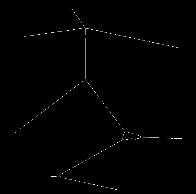
From here the strategy is this:
- Use the branch points of the web skeleton and its intersection points with the circular boundary to reconstruct corrupted/incomplete web gaps (like the smaller one in this case)
- Invert the reconstructed skeleton + the circular boundary (with some modifications)
- Get the web gap segments and measure their areas
Start by joining (as non-destructively as I could manage) the clean web skeleton with the circular boundary
webSkeletonPlusCirclePadded = ImagePad[#, 25, Black] & /@ {
    EdgeDetect@imageMask,
    webSkeletonCorrected
    } // ImageAdd


webPlusCircleSkeleton =
 Binarize[#, 10^-6] &@Thinning@ImageMultiply[#, imageMask] &@
      ImagePad[#, -25, Black] &@
    Binarize@GaussianFilter[#, 4] &@webSkeletonPlusCirclePadded
where webSkeletonPlusCirclePadded adds the circle and the web skeleton, and prepares some safe space for operations with ImagePad; a merged skeleton is then produced with webPlusCircleSkeleton by bridging the gaps using Gaussian filtering and binarization followed by thinning.
Then the branch points are found for the resulting skeleton:
allBranchPoints = MorphologicalBranchPoints@webPlusCircleSkeleton;

HighlightImage[
 webPlusCircleSkeleton,
 Style[#, Red] &@allBranchPoints
 ]
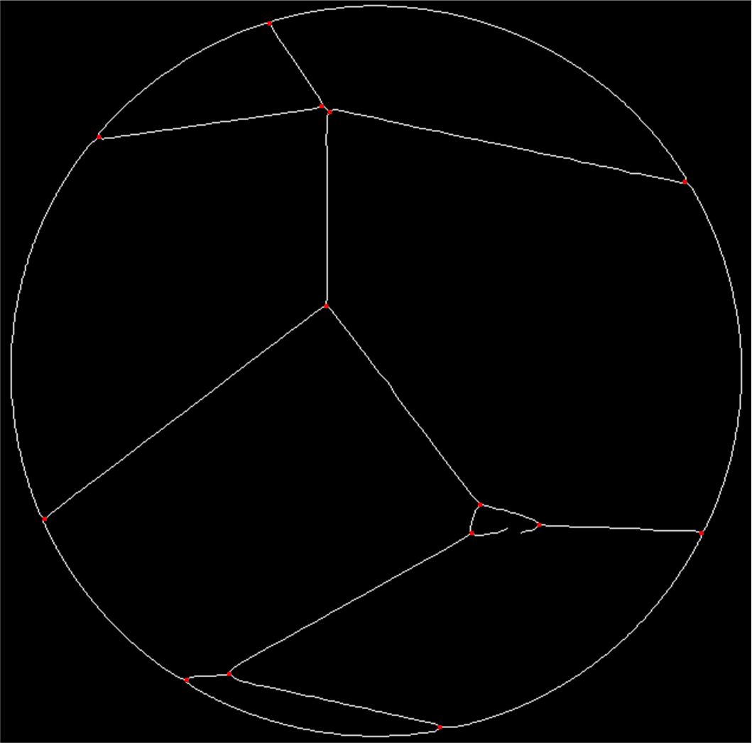
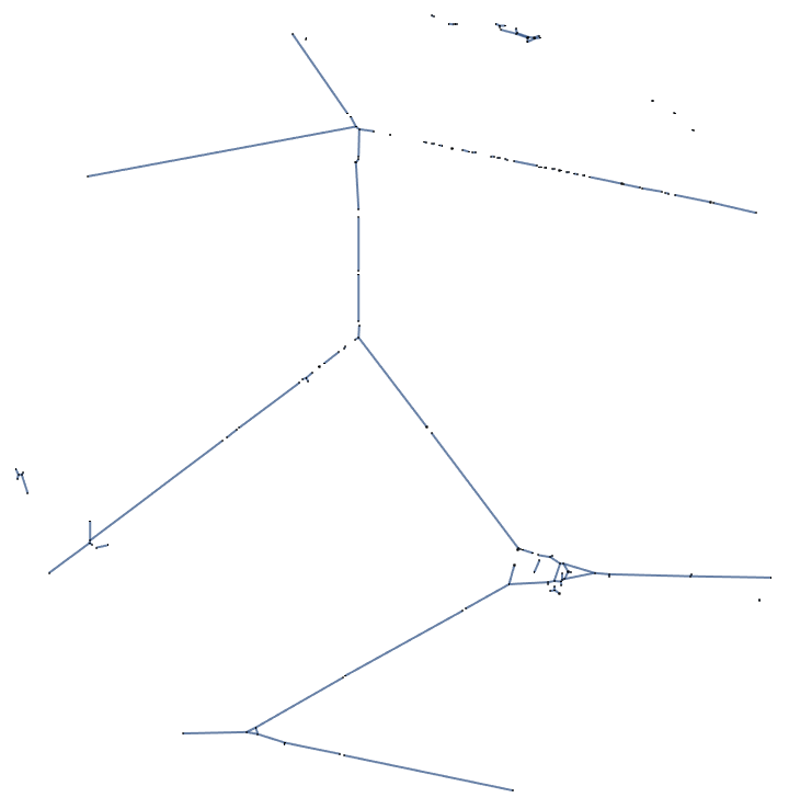
The fragments of incomplete edges are detected with
incompleteEdges =
 ImageDifference @@ {#, Pruning@#} &@webPlusCircleSkeleton
and the vertices that must be joined to reconstruct the missing edges are found via
verticesToJoin = ImageSubtract[#, incompleteEdges] &@
    DeleteSmallComponents[#, 1] &@ImageAdd[
   incompleteEdges,
   allBranchPoints
   ]
where ImageDifference @@ {#, Pruning@#} prunes the branches of incomplete edges to then find them as a difference from the unpruned image. verticesToJoin identifies branch points to be connected as those that are adjacent to the the branches of incomplete edges (DeleteSmallComponents[#, 1] removes all other points).
Here only one pair of vertices must be joined, but in general one would need to first identify pairs. Here the OP's idea with ImageLines could be useful, since the point pairs to be joined belong to branches of incomplete edges - their line orientations can be found (e.g. using RANSAC as a Method, since they may be rather jagged) and then pairs can be identified based on combined angle/Euclidean distances between their respective lines (i.e. using CosineDistance as a DistanceFunction).
Once that is done, the corrupted edges are recovered using the Bresenham's line algorithm (credit to @halirutan, Bresenham's line algorithm):
bresenhamLine[p0_, p1_] :=
 Module[{dx, dy, sx, sy, err, newp}, {dx, dy} = Abs[p1 - p0];
  {sx, sy} = Sign[p1 - p0];
  err = dx - dy;
  newp[{x_, y_}] :=
   With[{e2 = 2 err}, {If[e2 > -dy, err -= dy; x + sx, x],
     If[e2 < dx, err += dx; y + sy, y]}];
  NestWhileList[newp, p0, # =!= p1 &, 1]]

recoveredEdgePixelCoordinates =
  bresenhamLine @@ PixelValuePositions[#, 1] &@verticesToJoin;

recoveredEdges = ReplacePixelValue[
  verticesToJoin,
  # -> 1 & /@ recoveredEdgePixelCoordinates
  ]
allowing to finally get the solution skeleton:
webPlusCircleSkeletonFixed = ImageAdd[
  webPlusCircleSkeleton,
  -incompleteEdges,
  recoveredEdges
  ]
Perhaps there is a better way of doing this, but the web gaps can now be resolved as follows:
resolvedSegments =
  ColorNegate@Dilation[#, [email protected]] &@webPlusCircleSkeletonFixed;
and visualized like this:
resolvedSegmentsColorized =
 Colorize@MorphologicalComponents@resolvedSegments
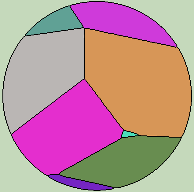
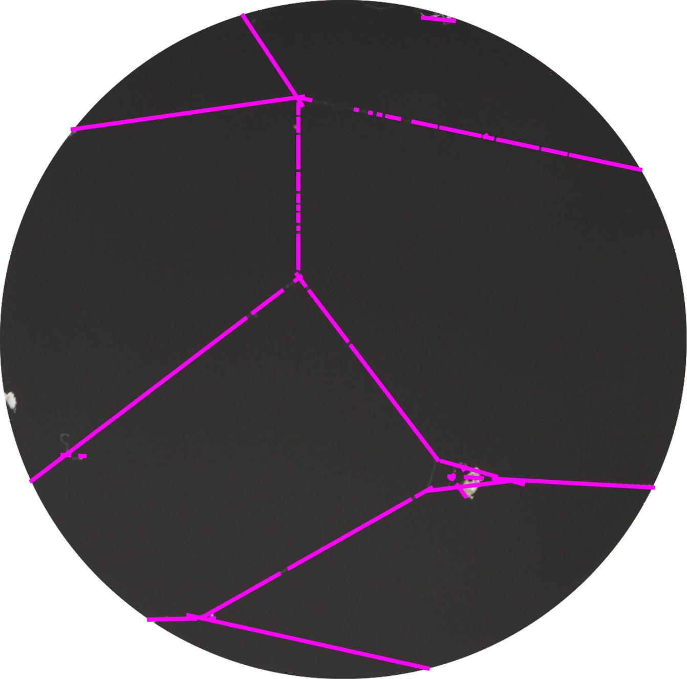
Alternatively, the very first image in this answer was generated with
finalSkeletonOverlay = ImageAdd[
  webInput,
  webPlusCircleSkeletonFixed
  ]
At last, the segment areas can be determined:
segmentStats = ComponentMeasurements[
     #, {"MaskedImage", "Area"}
     ] &@resolvedSegments;

Last /@ segmentStats[[2 ;; All]] // TableForm

But whether the quality is acceptable is, of course, for the OP to decide. This should be rather robust, but also has a few minor issues that are best answered in comments, should they become critical. Also, I would like to thank the OP for an interesting problem! Hope this helps.
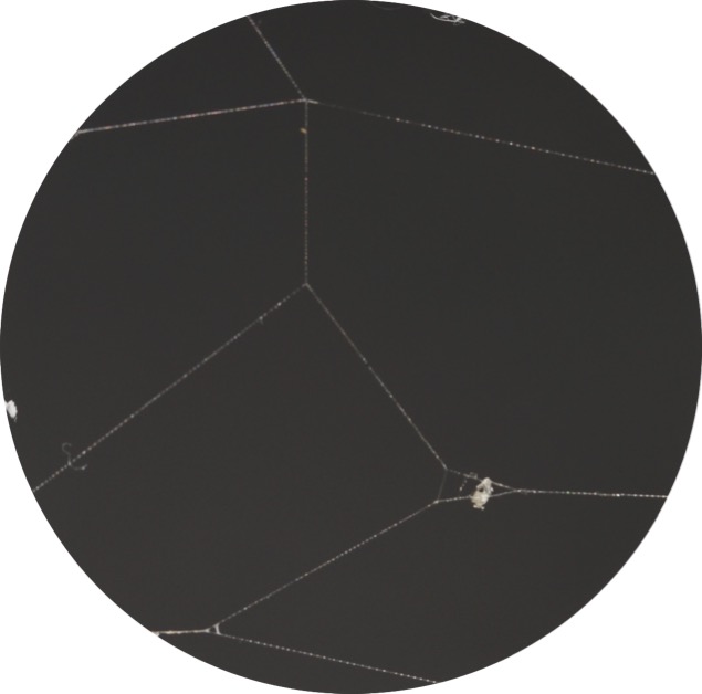 Note: I am a beginner to the Wolfram Language, and may be missing some basic knowledge on how to do this. I've added a sample image to this post, for reference.


Dilationto repair the lines, then invert the image and useMorphologicalComponentsto get the areas of the regions. Optionally,Thinningcould be applied afterDilation. I'm not at a computer with Mathematica at the moment so I can't try this out. $\endgroup$DeleteSmallComponents[LocalAdaptiveBinarize[img, 20], 2000]$\endgroup$