3
$\begingroup$

I would like to project a 3-dimensional cone onto a plane and mark the intersection (which is an ellipse) with a line. I find cone2 by performing a transformation on cone1:

cone1 = Cone[{{0, 0, 1}, {0, 0, 0}}];
transform = {{0.3, 0, 0.15}, {0, 0.35, 0}, {0.1, 0, 0.5}};
cone2 = GeometricTransformation[cone1, transform];

Now I would like to project cone2 through the origin onto the z = 1 plane. However, I cannot see a good way of directly performing this transformation in Mathematica. The best I can do is scale cone2 and then cut the graphic off at z = 1, thus:

origin = Point[{0, 0, 0}];
projcone2 = Scale[cone2, 3, {0, 0, 0}];

Graphics3D[{
   {Opacity[0.25], EdgeForm[{Thick}], cone1},
   {Opacity[0.6], Magenta, EdgeForm[Thick], cone2},
   {Opacity[0.6], Cyan, EdgeForm[Thick], projcone2},
   {PointSize[Large], origin}},
   Boxed -> False, PlotRange -> 1]

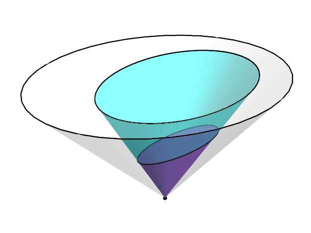
This gives:

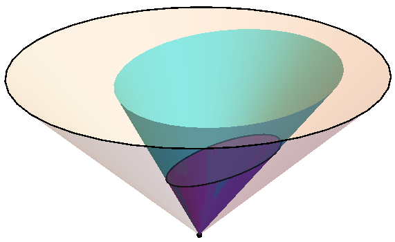
cone2 projected onto cone1

However, I would like the intersection of projcone2 and the base of cone1 to be marked with a line, just as the bases of cone1 and cone2 are. Possibly this could be achieved using this ellipse3D function. But finding the parameters that describe the ellipse in question is not entirely straightforward, and this whole method of scaling and cutting off seems like a bit of a hack anyway, so I would like to know if there is a better way.

I see that nonlinear transformation of regions is possible but have been unable to find anything for performing a nonlinear transformation on a 3D object.

The question

How can I correctly find the object projcone2 by implementing a transformation on cone2? By correctly, I mean that projcone2 should be exactly the 3D region required that is bounded by the z = 1 plane without having to artificially cut the image off there. Then the above code {Opacity[0.6], Cyan, EdgeForm[Thick], projcone2} would automatically display the desired intersection ellipse.

$\endgroup$
2

1 Answer 1

3
$\begingroup$

The only way I could find to add the ellipse you are asking for to your graphic was to compute a set of points along the ellipse and make line segments from them. Here is how I did it.

The following generates the graphic you show int the question.

origin = Point[{0, 0, 0}];
cone1 = Cone[{{0, 0, 1}, {0, 0, 0}}];
transform = {{0.3, 0, 0.15}, {0, 0.35, 0}, {0.1, 0, 0.5}};
cone2 = GeometricTransformation[cone1, transform];
projcone2 = Scale[cone2, {2.99, 2.99, 3}, {0, 0, 0}];

g1 = 
  Graphics3D[
    {{Opacity[0.25], EdgeForm[{Thick}], cone1}, 
     {Opacity[0.6], Magenta, EdgeForm[Thick], cone2}, 
     {Opacity[0.6], Cyan, EdgeForm[{Thick}], projcone2}, 
     {PointSize[Large], origin}},
    Boxed -> False,
    Lighting -> "Neutral",
    PlotRange -> {{-1, 1}, {-1, 1}, {0, 1}}];

And this generates the requested ellipse.

projPt[sourcPt_] := 
  Normal[
    Scale[
      GeometricTransformation[Point[sourcPt], transform], 
      {2.99, 2.99, 3}, {0, 0, 0}]][[1]]

With[{n = 72},
  ellipse = 
    Module[{z, pts, pairs},
      pts =
        Table[(z = projPt[{Cos[u], Sin[u], 1}])/z[[3]], {u, Subdivide[0, 2 π, n]}];
      pairs = Partition[pts, 2, 1];
      {Thick, Line[pairs]}]];

Putting the two graphics together gives

Show[g1, Graphics3D[ellipse], 
  PlotRangePadding -> {Automatic, Automatic, {.02, .006}},
  ImageSize -> 500]

cones

Update

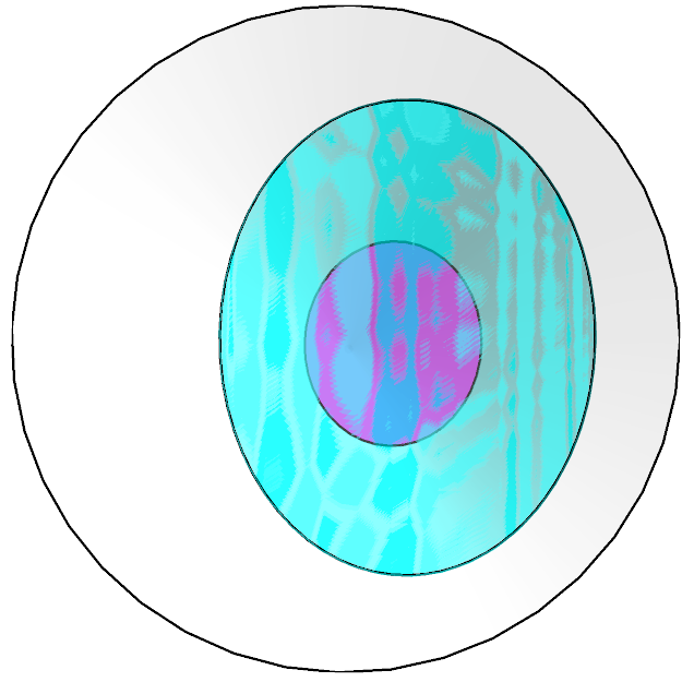
The OP insists that intersection of cone3 with the plane z == 1 be drawn as a distorted disk just so he can write something like

{Opacity[0.6], Cyan, EdgeForm[{Thick}], ellipse}

I will now demonstrate why I think that is a bad idea.

With[{n = 72},
  ellipse2 =
    Module[{pt, pts},
      pts =
       Table[(pt = projPt[{Cos[u], Sin[u], 1}])/pt[[3]], {u, Subdivide[0, 2 π, n]}];
      {Opacity[0.6], Cyan, EdgeForm[{Thick}], Polygon[pts]}]];

Show[cones, Graphics3D[ellipse2], 
  PlotRangePadding -> {Automatic, Automatic, {.02, .006}},
  ImageSize -> 500]

top_view

Note: this is my final word on this subject. Seeing how it is of little interest to anyone but the OP, I have already spent too much time on it.

$\endgroup$
3
  • $\begingroup$ Thanks very much. However, possibly I should have made one point clearer in the question: ideally projcone2 would have a base (as it would automatically if it could be generated by the appropriate transformation on cone2). Is it possible to fill in the ellipse you have plotted? (This would be possible using the ellipse3d solution I suggested in the question, if one could find the parameters that describe the ellipse.) $\endgroup$
    – Antony
    Commented Jul 13, 2016 at 12:50
  • 2
    $\begingroup$ @Antony. Are you saying you want the projcone2 to be a Mathematica Cone object. Not possible. All such objects are right circular cones by definition. projcone2 as you want it to be (and not as you have defined it) could be constructed laboriously from as large collection of triangles or as a triangular mesh. Another approach would be to find the correct geometric tranformation from cone1 into projcone2, but that is a math problem and not a Mathematica one. Perhaps you can solve that math problem. $\endgroup$
    – m_goldberg
    Commented Jul 13, 2016 at 16:46
  • $\begingroup$ I know that projcone2 cannot be a Cone object, but I would like it to behave as if you could define it as such an object. This would mean that the intersection ellipse would automatically be described by a surface that could easily be filled in Mathematica, instead of it being defined just by its boundary. If that is not possible then is there a good way to fill in the interior of the ellipse given by your parametrisation of its boundary? $\endgroup$
    – Antony
    Commented Jul 13, 2016 at 20:41

Your Answer

By clicking “Post Your Answer”, you agree to our terms of service and acknowledge you have read our privacy policy.

Not the answer you're looking for? Browse other questions tagged or ask your own question.