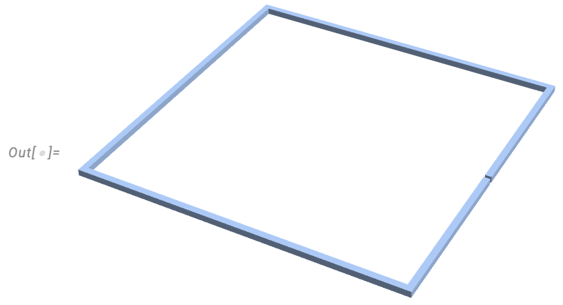
After using MM V12 for a long time on a MacBook Pro 2011, which just lost 8GB or RAM from 16GB, I am trying V14 on a MacMini M2pro with 32GB. I had previously coded a coupled 3D EM problem involving a rectangular wire loop driven by an AC voltage across a gap. The object being to view the quasi-static electric field (conservative plus non-conservative) in air around it and inside the conductor.
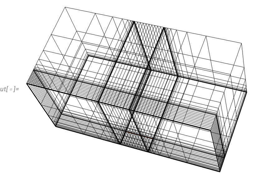
There are by admission much more efficient ways to do this, but I wanted to see if with FEM I got similar results to ANSYS Maxwell, which by the way cannot solve E-field and H-Field simultaneously due to the use of decoupled solvers. The coupled problem is notoriously ill-conditioned at low frequencies apparently. Anyway, that is not the problem. I have a code version in which the mesh is ca. 27000 tetrahedral elements created by OpenCascadeLink, and that solves OK in V14 on the M2. What surprised me is that in MM I found in the guides that I was able to apply an excitation on the conductor face that was not on the mesh boundary - cool. The field plots for tetrahedral are smooth, but it does not capture the skin effect in the conductor well. To improve that I also have a graded hexahedron mesh in which I used code from Tim Laska in a number of posts:
How to Improve FEM Solution with NDSolve?
In V14 grading the mesh should be easier due to new added features, but I have not implemented it. The code below ran fine on my old MacBook Pro (Intel) while it had 16GB, but it took a while. If I reduce the mesh from 55000 to 16700 it will run on 8GB with a little swap space still needed. The advantage of the hexahedron mesh is it can start to capture the skin effect better in the conductor.
But on v14 on a new Mac mini it eats through memory like crazy and does not finish. In fact I have access to two M2 mini's. One with 16GB and one with 32GB. On the 16GB machine, when I use the 55000 element mesh (nsd=3, nl=4, nw=15, na=15) after 16secs I thought it had solved, but I was still looking at previously solved result plots. I suspect it just hit a memory limit and stopped the kernel. Once it left the NDSolveValue function all variables appear to be cleared by the software.
On the 32GB machine and just the 16700 element mesh (nsd=2, nl=3, nw=10, na=10) it just rapidly consumes memory, such that even with 32GB it is using swap space and after a minute or so it is clear it has problems so I just quit the Kernel.
So I do not know if it is a problem with the Apple Silicon implementation or V14, and why just hexahedron elements. Like I said a tetrahedral version I have works and the hexahedral version worked on V12 with Apple Intel. The wire loop was implemented with 1/4 symmetry and sits in the xy plane at the bottom/middle of the figure below where all the fine mesh is. The rest is air. Permeability and permittivity are constant everywhere.
16700 element Hexahedral Code
3D FEM Rectangular Current Loop
Clear["Global`*"];
Needs["NDSolve`FEM`"];
Needs["OpenCascadeLink`"];

cw = 0.02; (*wire conductor X-section width/height*)
cl = 1.0; (*rectangular coil length,center to center of wire*)
gap = 0.01; (*gap between feed conductors*)
hAir = 6.0*cl; (*height/depth air region*)
Vapplied = 100.0;(* +/- voltage applied to each feed wire end*)
\[Mu]o = 4.0*\[Pi]*10^-7; (*is constant everywhere*)
\[Epsilon]o = 8.854*10^-12;(*is constant everywhere*)
\[Omega] = 2.0*\[Pi]*60000; (*frequency of applied voltage*)
\[Sigma]cu = 5.8*10^7;(*conductivity of wire conductor*)
nsd = 2;  (*number of mesh points to subdivide the skin depth at \
conductor surface by*)
nl = 3; (*number of additional mesh points in half a conductor width \
cw/2*)
nw = 10; (*number of wire divisions along each wire part*)
na = 10; (*number of mesh points to divide the AirRegion of length \
hAir/2 in*)
ng = 2; (*number of mesh points in the gap*)
fap = 0.01; (*distance to first graded mesh points air region*)
fcf = 5; (*distance to first graded mesh point in conductor region as \
a multiple of skin depths*)
sd = Sqrt[2/(\[Omega]*\[Sigma]cu*\[Mu]o)];
cr = cl/2;
(*draw conductor*)
wire1Shape =
  Cuboid[{cr + cw/2, gap/2, -cw/2}, {cr - cw/2, cr + cw/2, cw/2}];
wire2Shape =
  Cuboid[{cr + cw/2, cr - cw/2, -cw/2}, {-cr - cw/2, cr + cw/2, cw/2}];
wire3Shape =
  Cuboid[{-cr - cw/2, cr + cw/2, -cw/2}, {-cr + cw/2, 0, cw/2}];
wireHalfReg =
  RegionUnion[Region[wire1Shape], Region[wire2Shape],
   Region[wire3Shape]];
wireMirrorReg =
  TransformedRegion[wireHalfReg, RotationTransform[Pi, {1, 0, 0}]];
wireReg = RegionUnion[wireHalfReg, wireMirrorReg]

(*Model just 1/4 of the problem using symmetry. Use these functions \
by Tim Laska - slightly modified*)
rateFunc[x0_, xf_, n_, r_,
   j_] := (xf - x0)*(r^(j/(-1 + n)) - 1.)/(r - 1.) + x0;
meshGrowth[x0_, xf_, n_, r_] :=
  Table[rateFunc[x0, xf, n, r, j], {j, 0, n - 1}];
findGrowthRate[x0_, xf_, n_, fElm_] :=
  Quiet@Abs@
    FindRoot[rateFunc[x0, xf, n, r, 1] - fElm, {r, 1.1, 100000},
      Method -> "Brent"][[1, 2]];
meshGrowthByElm[x0_, xf_, n_, fElm_] :=
  N@Sort@Chop@meshGrowth[x0, xf, n, findGrowthRate[x0, xf, n, fElm]];
meshGrowthByElm0[len_, n_, fElm_] :=
  meshGrowthByElm[0.0, len, n, fElm];
flipSegment[l_] := (#1 - #2) & @@ {First[#], #} &@Reverse[l] +
   l[[1]];
pointsToMesh[data_] :=
  MeshRegion[Transpose[{data}],
   Line@Table[{i, i + 1}, {i, Length[data] - 1}]];

(*X mesh points*)
pointsX = {-hAir/2, -cr - cw/2, -cr + cw/2, cr - cw/2, cr + cw/2,
   hAir/2};
pointsAir1X =
  meshGrowthByElm[-cr - cw/2, -hAir/2, na, -cr - cw/2 - fap];
pointsSkin1X = Subdivide[-cr - cw/2, -cr - cw/2 + sd, nsd];
pointsCond1X =
  meshGrowthByElm[-cr - cw/2 + sd, -cr, nl, -cr - cw/2 + fcf*sd];
pointsCond2X =
  meshGrowthByElm[-cr + cw/2 - sd, -cr, nl, -cr + cw/2 - fcf*sd];
pointsSkin2X = Subdivide[-cr + cw/2 - sd, -cr + cw/2, nsd];
pointsWire1X = Subdivide[-cr + cw/2 + sd, cr - cw/2 - sd, nw];
pointsSkin3X = Subdivide[cr - cw/2, cr - cw/2 + sd, nsd];
pointsCond3X =
  meshGrowthByElm[cr - cw/2 + sd, cr, nl, cr - cw/2 + fcf*sd];
pointsCond4X =
  meshGrowthByElm[cr + cw/2 - sd, cr, nl, cr + cw/2 - fcf*sd];
pointsSkin4X = Subdivide[cr + cw/2 - sd, cr + cw/2, nsd];
pointsAir2X =
  meshGrowthByElm[cr + cw/2, hAir/2, na, cr + cw/2 + fap];
pointsX =
  Union[pointsX, pointsAir1X, pointsSkin1X, pointsCond1X,
   pointsCond2X, pointsSkin2X, pointsWire1X, pointsSkin3X,
   pointsCond3X, pointsCond4X, pointsSkin4X, pointsAir2X];
segX = pointsToMesh[pointsX]

(*Y mesh points*)
pointsY = {0.0, gap/2, gap/2 + cw/2, cr - cw/2, cr + cw/2, hAir/2};
pointsGapY = Subdivide[gap/2, ng];
pointsWireY = Subdivide[gap/2 + cw, cr - cw/2, nw];
pointsSkin3Y = Subdivide[cr - cw/2, cr - cw/2 + sd, nsd];
pointsCond3Y =
  meshGrowthByElm[cr - cw/2 + sd, cr, nl, cr - cw/2 + fcf*sd];
pointsCond4Y =
  flipSegment@meshGrowthByElm[cr, cr + cw/2 - sd, nl, cr + fcf*sd];
pointsSkin4Y = Subdivide[cr + cw/2 - sd, cr + cw/2, nsd];
pointsAirY = meshGrowthByElm[cr + cw/2, hAir/2, na, cr + cw/2 + fap];
pointsY =
  Union[pointsY, pointsGapY, pointsWireY, pointsSkin3Y, pointsSkin3Y,
   pointsSkin3Y, pointsSkin4Y, pointsAirY];
segY = pointsToMesh[pointsY]


(*Z mesh points*)
pointsZ = {0.0, cw/2, hAir/2};
pointsCondZ = flipSegment@meshGrowthByElm0[cw/2 - sd, nl, fcf*sd];
pointsSkinZ = Subdivide[cw/2 - sd, cw/2, nsd];
pointsAirZ = meshGrowthByElm[cw/2, hAir/2, na, cw/2 + fap];
pointsZ = Union[pointsZ, pointsCondZ , pointsSkinZ, pointsAirZ];
segZ = pointsToMesh[pointsZ]

(*Look at conductor cross section meshing*)
condX = pointsToMesh@
   Union[pointsSkin1X, pointsCond1X, pointsCond2X, pointsSkin2X];
condZ = pointsToMesh@Union[pointsCondZ , pointsSkinZ];
a = RegionProduct[condX, condZ];
HighlightMesh[a, Style[1, Orange]]

(*Look at conductor cross section meshing*)
condY = pointsToMesh@
   Union[pointsSkin3Y, pointsCond3Y, pointsCond4Y, pointsSkin4Y];
condZ = pointsToMesh@Union[pointsCondZ , pointsSkinZ];
a = RegionProduct[condY, condZ];
HighlightMesh[a, Style[1, Orange]]

(*Look at conductor cross section meshing*)
condX = pointsToMesh@
   Union[pointsSkin3X, pointsCond3X, pointsCond4X, pointsSkin4X];
condZ = pointsToMesh@Union[pointsCondZ , pointsSkinZ];
a = RegionProduct[condX, condZ];
HighlightMesh[a, Style[1, Orange]]

(*Make 3D 1/4 Region*)
regTotal = RegionProduct[segX, segY, segZ];
HighlightMesh[regTotal, Style[1, Orange]]

crd = MeshCoordinates[regTotal];
inc = Delete[0] /@ MeshCells[regTotal, 3];
halfWire =
  Graphics3D[{Orange, {wire1Shape, wire2Shape, wire3Shape}},
   Boxed -> False];

mesh = ToElementMesh["Coordinates" -> crd,
  "MeshElements" -> {HexahedronElement[inc]}]
Show[halfWire, mesh["Wireframe"]]

(*define coil conductive region*)
reg1 = 0 <= z <= cw/2;
reg2 = (cr - cw/2) <= x <= (cr + cw/2) && (gap/2) <=
    y <= (cr + cw/2);
reg3 = (-cr - cw/2) <= x <= (cr - cw/2) && (cr - cw/2) <=
    y <= (cr + cw/2);
reg4 = (-cr - cw/2) <= x <= (-cr + cw/2) && 0 <= y <= cr - cw/2;
reg5 = (cr - cw/2) <= x <= (cr + cw/2) && y < gap/2 &&
   reg1; (*gap region has no conductivity*)
\[Sigma] =
  Piecewise[{{\[Sigma]cu, reg1 && (reg2 || reg3 || reg4) && ! reg5}},
   10]; (*conductivity*)

(*define magnetic vector potential*)
mvpA = {mvpAx[x, y, z], mvpAy[x, y, z], mvpAz[x, y, z]};

(*Assign magnetic vector potential on problem boundary, set A x n = 0 \
for to enforce tangential magnetic flux, except on z=0 where flux is \
normal*)
\[CapitalGamma]d1 = {DirichletCondition[mvpAx[x, y, z] == 0,
    y == 0 || y == hAir/2 || z == hAir/2],
   DirichletCondition[mvpAy[x, y, z] == 0,
    x == hAir/2 || x == -hAir/2 || z == hAir/2],
   DirichletCondition[mvpAz[x, y, z] == 0,
    x == -hAir/2 || x == hAir/2 || y == 0 || y == hAir/2 || z == 0]};

(*Scalar voltage potential on wire ends*)
\[CapitalGamma]d2 = {DirichletCondition[v[x, y, z] == 0, y == 0],
   DirichletCondition[v[x, y, z] == Vapplied,
    cr - cw/2 <= x <= cr + cw/2 && y == gap/2 &&
     0 \[LessSlantEqual] z \[LessSlantEqual] cw/2]};

(*define Coulomb gauged pde operators*)
op1 = Laplacian[
    mvpA, {x, y, z}] - \[Mu]o*(\[Sigma] + I*\[Omega]*\[Epsilon]o)*
    Grad[v[x, y, z], {x, y,
      z}] - \[Mu]o*(I*\[Omega]*\[Sigma] - \[Omega]^2*\[Epsilon]o)*mvpA;
op2 = Div[(\[Sigma] + I*\[Omega]*\[Epsilon]o)*
     Grad[v[x, y, z], {x, y, z}] - I*\[Omega]*\[Sigma]*mvpA, {x, y,
    z}];

(*Solve*)
soln = {potAx, potAy, potAz, potV} =
   NDSolveValue[{op1 == {0, 0, 0},
     op2 == 0, \[CapitalGamma]d1, \[CapitalGamma]d2}, {mvpAx, mvpAy,
     mvpAz, v}, {x, y, z} \[Element] mesh,
    Method -> {"FiniteElement",
      InterpolationOrder -> {mvpAx -> 1, mvpAy -> 1, mvpAz -> 1,
        v -> 1}}];
(*Electric Field*)
ex = -D[potV[x, y, z], x] - potAx[x, y, z]*I*\[Omega];
ey = -D[potV[x, y, z], y] - potAy[x, y, z]*I*\[Omega];
ez = -D[potV[x, y, z], z] - potAz[x, y, z]*I*\[Omega];

(*Results*)
Plot[{Re[ex] /. {x -> a, y -> 1, z -> 0},
  Re[ey] /. {x -> a, y -> 1, z -> 0},
  Re[ez] /. {x -> a, y -> 1, z -> 0}}, {a, -hAir/2, hAir/2},
 AxesLabel -> {"x distance (m)", "(V/m)"},
 PlotLabel -> "Electric Field along x-dir line at y=1.0m and z=0m ",
 PlotRange -> Full]

Plot[{Re[ex] /. {x -> -1, y -> a, z -> 0},
  Re[ey] /. {x -> -1, y -> a, z -> 0},
  Re[ez] /. {x -> -1, y -> a, z -> 0}}, {a, 0, hAir/2},
 AxesLabel -> {"y distance (m)", "(V/m)"},
 PlotLabel -> "Electric Field along y-dir line at x=-1.0m and z=0m ",
 PlotRange -> Full]

Plot[Re[potV[x, y, z]] /. {x -> a, y -> 1, z -> 0}, {a, -hAir/2,
  hAir/2}, AxesLabel -> {"x distance (m)", "(V/m)"},
 PlotLabel -> "Scalar Potential along x-dir line at y=1.0m and z=0m ",
  PlotRange -> Full]
I am at a loss, I was planning to upgrade to V14 (computer is already purchased!), but this is a problem for me. Any suggestions to possible reasons and/or work around? I would be interested to hear if others can run the code and on what platform.
Regards
Andrew


