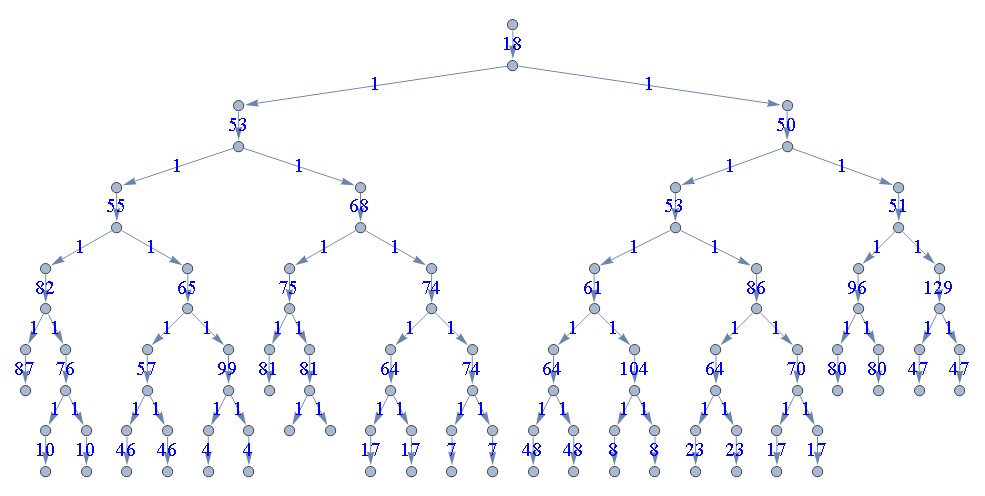
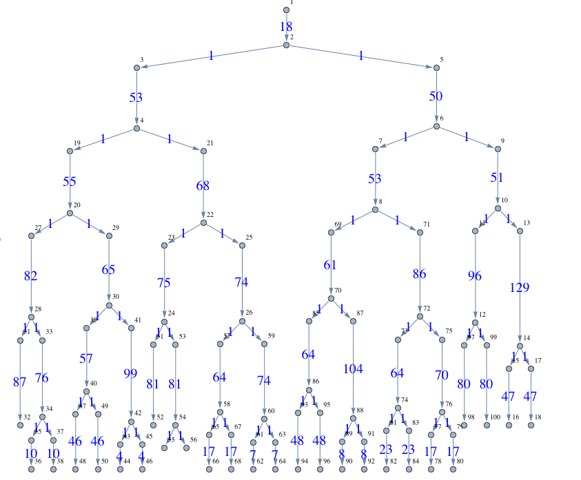
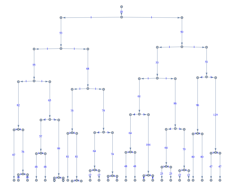
I love using Graph as structure to store and visualize my data in Mathematica. Consider the following simple example for creating a Graph object with weighted directed edges. I already laid out the graph in a tree structure using the options {"LayeredEmbedding", "Orientation" -> Top, "RootVertex" -> 1} I found in the documentation of GraphLayout, since this representation is useful for my particular needs.
vertices={1,2,3,4,5,6,7,8,9,10,11,12,13,14,15,16,17,18,19,20,21,22,23,24,25,26,27,28,29,30,31,32,33,34,35,36,37,38,39,40,41,42,43,44,45,46,47,48,49,50,51,52,53,54,55,56,57,58,59,60,61,62,63,64,65,66,67,68,69,70,71,72,73,74,75,76,77,78,79,80,81,82,83,84,85,86,87,88,89,90,91,92,93,94,95,96,97,98,99,100};
edges={1\[DirectedEdge]2,3\[DirectedEdge]4,5\[DirectedEdge]6,7\[DirectedEdge]8,9\[DirectedEdge]10,11\[DirectedEdge]12,13\[DirectedEdge]14,15\[DirectedEdge]16,17\[DirectedEdge]18,19\[DirectedEdge]20,21\[DirectedEdge]22,23\[DirectedEdge]24,25\[DirectedEdge]26,27\[DirectedEdge]28,29\[DirectedEdge]30,31\[DirectedEdge]32,33\[DirectedEdge]34,35\[DirectedEdge]36,37\[DirectedEdge]38,39\[DirectedEdge]40,41\[DirectedEdge]42,43\[DirectedEdge]44,45\[DirectedEdge]46,47\[DirectedEdge]48,49\[DirectedEdge]50,51\[DirectedEdge]52,53\[DirectedEdge]54,57\[DirectedEdge]58,59\[DirectedEdge]60,61\[DirectedEdge]62,63\[DirectedEdge]64,65\[DirectedEdge]66,67\[DirectedEdge]68,69\[DirectedEdge]70,71\[DirectedEdge]72,73\[DirectedEdge]74,75\[DirectedEdge]76,77\[DirectedEdge]78,79\[DirectedEdge]80,81\[DirectedEdge]82,83\[DirectedEdge]84,85\[DirectedEdge]86,87\[DirectedEdge]88,89\[DirectedEdge]90,91\[DirectedEdge]92,93\[DirectedEdge]94,95\[DirectedEdge]96,97\[DirectedEdge]98,99\[DirectedEdge]100,2\[DirectedEdge]3,2\[DirectedEdge]5,6\[DirectedEdge]7,6\[DirectedEdge]9,10\[DirectedEdge]11,10\[DirectedEdge]13,14\[DirectedEdge]15,14\[DirectedEdge]17,4\[DirectedEdge]19,4\[DirectedEdge]21,22\[DirectedEdge]23,22\[DirectedEdge]25,20\[DirectedEdge]27,20\[DirectedEdge]29,28\[DirectedEdge]31,28\[DirectedEdge]33,34\[DirectedEdge]35,34\[DirectedEdge]37,30\[DirectedEdge]39,30\[DirectedEdge]41,42\[DirectedEdge]43,42\[DirectedEdge]45,40\[DirectedEdge]47,40\[DirectedEdge]49,24\[DirectedEdge]51,24\[DirectedEdge]53,54\[DirectedEdge]55,54\[DirectedEdge]56,26\[DirectedEdge]57,26\[DirectedEdge]59,60\[DirectedEdge]61,60\[DirectedEdge]63,58\[DirectedEdge]65,58\[DirectedEdge]67,8\[DirectedEdge]69,8\[DirectedEdge]71,72\[DirectedEdge]73,72\[DirectedEdge]75,76\[DirectedEdge]77,76\[DirectedEdge]79,74\[DirectedEdge]81,74\[DirectedEdge]83,70\[DirectedEdge]85,70\[DirectedEdge]87,88\[DirectedEdge]89,88\[DirectedEdge]91,86\[DirectedEdge]93,86\[DirectedEdge]95,12\[DirectedEdge]97,12\[DirectedEdge]99};
weights={18,53,50,53,51,96,129,47,47,55,68,75,74,82,65,87,76,10,10,57,99,4,4,46,46,81,81,64,74,7,7,17,17,61,86,64,70,17,17,23,23,64,104,8,8,48,48,80,80,1,1,1,1,1,1,1,1,1,1,1,1,1,1,1,1,1,1,1,1,1,1,1,1,1,1,1,1,1,1,1,1,1,1,1,1,1,1,1,1,1,1,1,1,1,1,1,1,1,1};

Graph[vertices, edges, EdgeWeight -> weights,
  EdgeLabels -> MapThread[Rule, {edges, weights}],
  GraphLayout -> {"LayeredEmbedding", "Orientation" -> Top,
    "RootVertex" -> 1}, EdgeLabelStyle -> Directive[Blue, 20]]
The graph that I get with these options looks like the following:

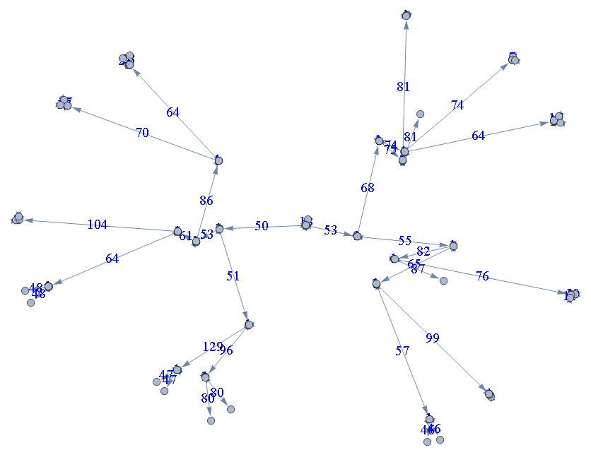
Edge weights are put as labels but all edges have the same length due to the options specified. What I would like to obtain now is a Graph object with edges scaled according to the edge weight while keeping the tree-like layout of the graph. I have read the documentation of GraphLayout and several other documentation pages on EdgeWeight, TreeGraph, etc. The only possibility I found so far is to use the options {"SpringElectricalEmbedding", "EdgeWeighted"->True} for the Graph object. However this destroys the tree-like layout I want to keep:
 Graph[vertices, edges, EdgeWeight -> weights,
 EdgeLabels -> MapThread[Rule, {edges, weights}],
 GraphLayout -> {"SpringElectricalEmbedding", "EdgeWeighted" -> True},EdgeLabelStyle -> Directive[Blue, 20]]
And the Graph object looks like this:

Question: Is there a way to combine the tree-like layout of Graph with weight-scaled edges in Mathematica?
I think one would have to change the VertexCoordinates that are embedded in the Graph. It is easy to access the current VertexCoordinates using GraphEmbedding but I can't figure out how to change them appropriately.


SpringEmbeddingandSpringElectricalEmbeddingtakeEdgeWeighted. More details here: Graphs with weight in 2D and 3D $\endgroup${"SpringElectricalEmbedding", EdgeWeighted"->True}forGraphLayout(see second graph above). But, I would like to keep a tree-like structure of theGraphwhile using the edge weights. $\endgroup$