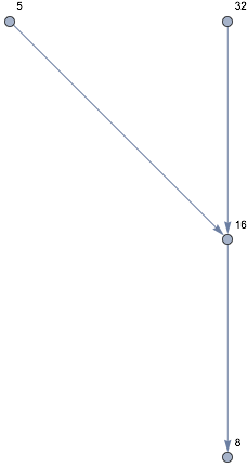
Update 2: Another attempt:
pos[{t1, t2, ...}, {u, v}] gives the starting position {x, y} that connects to the final position {u, v} if we follow the angle path {t1, t2, ...}. For a non-sink vertex v the path of angles is found by replacing the vertices on the shortest path from v to 1 with ϕ + θ or ϕ - θ depending on parity.
ClearAll[pos, angleList, vcoord]
pos[t:{__}, {u_, v_}] := {u, v} - Total[Through @ {Cos, Sin} @ Accumulate[t], {2}]
angleList[g_, v_, ϕ_, t_] := ϕ +  Most[FindShortestPath[g, v, 1]] /.
   {u_?EvenQ -> t, u_?OddQ -> - t}
vcoord[g_, v_, ϕ_, t_, pos1_: {0, 0}] := pos[angleList[g, v, ϕ, t], pos1]
Examples:
vk = 20;
edges = (DirectedEdge @@@ Partition[Collatz[#], 2, 1]) & /@ Range[vk] // Flatten // Union;
g = Graph[edges];
ϕ = 0;
θ = Pi/32;
Graph[edges,
    VertexCoordinates -> {1 -> {0, 0}, v_ :> vcoord[g, v, ϕ, θ]},
     ImagePadding -> 20, EdgeStyle -> Arrowheads[Small],
     VertexShapeFunction -> "Name", AspectRatio -> 2,
     ImageSize -> 500]
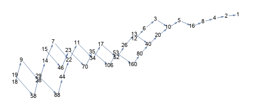
With vk = 500 and
Graph[edges,
   VertexCoordinates -> {1 -> {0, 0}, v_ :> vcoord[g, v, ϕ, θ]},
    ImagePadding -> 20, EdgeStyle -> Arrowheads[Tiny],
    VertexShapeFunction ->None, AspectRatio -> 2,   ImageSize -> 500]
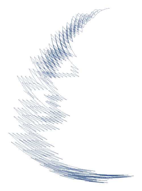
Using
VertexCoordinates -> {1 -> {0, 0}, v_ :> vcoord[g, v, ϕ, 2 θ]}
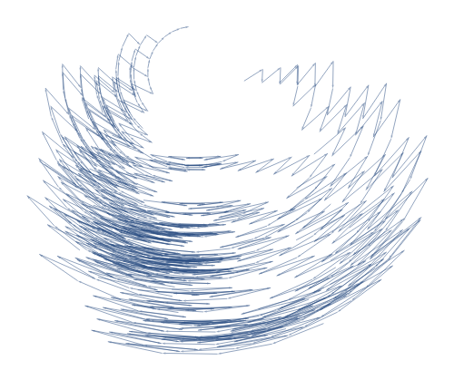
With vk = 600 and adding the options
EdgeShapeFunction -> "CurvedArc",
EdgeStyle -> {e_ :> Directive[RandomColor[], AbsoluteThickness[5], CapForm["Round"]]
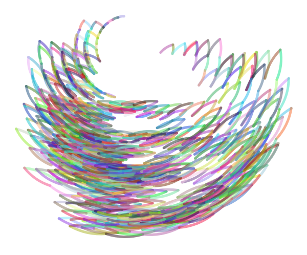
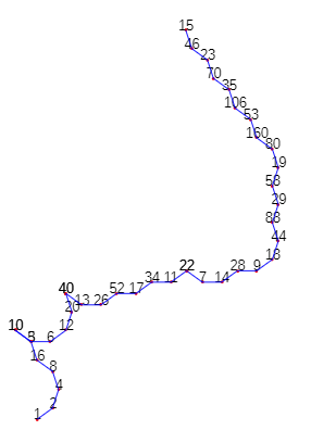
Update: -- this is not quite correct --- (1) Reverse the edges in Collatz tree, (2) use DepthFirstScan get an ordered list of vertices, (3) split the list at branch points, (4) assign θ or -θ to each element of the list based on its parity, (5) Fold AnglePath on the resulting list of lists:
ClearAll[anglePath]
Options[anglePath] := {VertexLabels -> False, InitialCoords -> {{0, 0}, 0}};

anglePath[g_, θ_, opts : OptionsPattern[{anglePath, Graphics}]] :=
 Module[{pieces = Split[Flatten @ Reap[DepthFirstScan[g, 1,
  {"PrevisitVertex" -> (If[Length @ VertexOutComponent[g, #, 1] == 3,
     Sow[{#, #}], Sow[#]] &)} ]][[2, 1]], Unequal], angles, path},
  angles = θ ( Mod[pieces, 2] + 1 /. 2 -> -1);
  path = Join @@ Rest[FoldList[AnglePath[Last[#], Rest@#2] &,
     {OptionValue[InitialCoords]}, angles]];
  Graphics[{Red,  Point @ path, Black,
    OptionValue[VertexLabels] /.
      {True -> MapThread[Text[Style[#, 14], #2] &, {Join @@ pieces, path} ], _ -> {}},
     Blue, Line@ path}, FilterRules[{opts}, Options[Graphics]]]]
Examples:
vk = 20;
edges = (DirectedEdge @@@ Partition[Collatz[#], 2, 1]) & /@  Range[vk] //
   Flatten // Union;
g = Graph[Reverse /@ edges];

anglePath[g, Pi/5, VertexLabels -> True, ImageSize -> 400, ImagePadding -> 10]
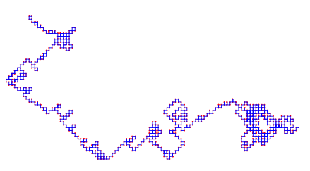
vk = 500;
edges = (DirectedEdge @@@ Partition[Collatz[#], 2, 1]) & /@
     Range[vk] // Flatten // Union;
g = Graph[Reverse /@ edges];

anglePath[g, Pi/2, BaseStyle -> PointSize[Tiny], ImageSize -> 500,
 ImagePadding -> 10]
With vk = 3000 and
 anglePath[g, 2 Pi/5, BaseStyle -> PointSize[Tiny], ImageSize -> 700,
   ImagePadding -> 10]

Original answer:
Perhaps:
Using this answer by Sjoerd C. de Vries to construct a Collatz sequence:
ClearAll[Collatz]
Collatz[1] := {1}
Collatz[n_Integer]  := Prepend[Collatz[3 n + 1], n] /; OddQ[n] && n > 0
Collatz[n_Integer] := Prepend[Collatz[n/2], n] /; EvenQ[n] && n > 0

vk =  15;
edges = (DirectedEdge @@@ Partition[Collatz[#], 2, 1]) & /@ Range[vk] // Flatten // Union;

g = Graph[edges,
   GraphLayout -> {"LayeredDigraphDrawing", "Orientation" -> Top},
   ImagePadding -> 10, EdgeStyle -> Arrowheads[Small],
   VertexShapeFunction -> "Name", AspectRatio -> 2, ImageSize -> 300];
We take the vertical component of a vertex as its distance to the sink vertex and the vertical distance between layers as 1. So instead of working with angles we can work with horizontal displacements from 0 as input to the vertex layout process.
ClearAll[vc]
vc[g_, Δ_] := First[#] -> {Δ If[EvenQ @ First @ #, 1, -1] + Δ (Count[Rest @ #, _?EvenQ] -
  Count[Rest @ #, _OddQ]), Length @ #} & /@ (VertexOutComponent[g, #] & /@ VertexList[g])

g2 = Graph[edges, VertexCoordinates -> vc[g, 1/4],
   ImagePadding -> 10, EdgeStyle -> Arrowheads[Small],
   VertexShapeFunction -> "Name", ImageSize -> 300, AspectRatio -> 2];

Row[{g, g2}, Spacer[10]]
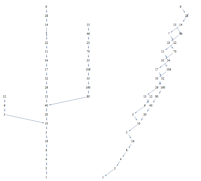
Note: For larger vk (e.g., vk = 20) some vertices will overlap.

