2
$\begingroup$

EDIT2 the answers here (How to compute intersections of circles on a lattice) seem like they could help or solve the problem.


EDIT: I saw this question about finding regions between lines before I asked. The ImageMesh solution can work but there is some re-scaling involved because the scale is not conserved when moving from a graphics object to an image. Other solutions explicitly or implicitly rely on the existence of infinite lines. If it is safe to extend the lines to infinite lines then one can obtain the desired domain using :

RegionDifference[BoundingRegion@RegionUnion@lines, RegionUnion@ReplaceAll[Line->InfiniteLine]@lines]

That is not the case of the first example below as that would add extra squares by "completing" the figure within the bounding region.

That said if one is interested in the scenario where the shape is regular and it is safe to extend the lines within the bounding region then one can also use the cylindrical decomposition. It might be necessary to rationalize the equations before applying the decomposition (I did not and got an error). For example like this :

RegionDifference[BoundingRegion@RegionUnion@lines, 
    RegionUnion@ReplaceAll[Line -> InfiniteLine]@lines] // 
   Refine[RegionMember[#, {x, y}], Element[x | y, Reals]] & // 
  Rationalize[#, 0] &  // 
 CylindricalDecomposition[#, {x, y}, "Components"] &

Other solutions use HalfSpace this also relies on the existence of an infinite line.

The method using graphs in that question might work but I did not try long enough to understand it.


I would like the following input/output:

Input:

A list of geometric lines

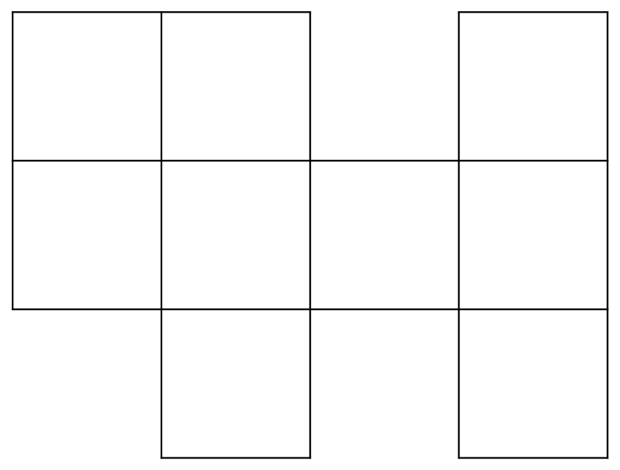
Example 1:

ArrayMesh[{{1, 1, 0, 1}, {1, 1, 1, 1}, {0, 1, 0, 1}}] // 
MeshPrimitives[#, 1] &

{Line[{{1.,2.},{1.,3.}}],Line[{{1.,3.},{0.,3.}}],Line[{{0.,3.},{0.,2.}}],Line[{{0.,2.},{1.,2.}}],Line[{{2.,2.},{2.,3.}}],Line[{{2.,3.},{1.,3.}}],Line[{{1.,2.},{2.,2.}}],Line[{{4.,2.},{4.,3.}}],Line[{{4.,3.},{3.,3.}}],Line[{{3.,3.},{3.,2.}}],Line[{{3.,2.},{4.,2.}}],Line[{{1.,1.},{1.,2.}}],Line[{{0.,2.},{0.,1.}}],Line[{{0.,1.},{1.,1.}}],Line[{{2.,1.},{2.,2.}}],Line[{{1.,1.},{2.,1.}}],Line[{{3.,1.},{3.,2.}}],Line[{{3.,2.},{2.,2.}}],Line[{{2.,1.},{3.,1.}}],Line[{{4.,1.},{4.,2.}}],Line[{{3.,1.},{4.,1.}}],Line[{{2.,0.},{2.,1.}}],Line[{{1.,1.},{1.,0.}}],Line[{{1.,0.},{2.,0.}}],Line[{{4.,0.},{4.,1.}}],Line[{{3.,1.},{3.,0.}}],Line[{{3.,0.},{4.,0.}}]}

lines

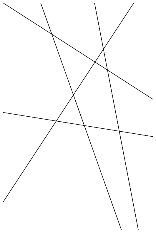
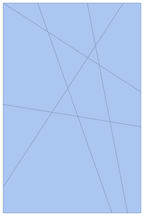
Example 2

{Line[{{0., 92.2227}, {431.147, 750.}}], 
 Line[{{301.72, 750.}, {446.159, 0.}}], 
 Line[{{123.934, 750.}, {390.253, 0.}}], 
 Line[{{494., 432.03}, {0.470817, 750.}}], 
 Line[{{0., 388.081}, {494., 308.166}}]}

lines2

Output:

In simple words, I would like the squares/tiles in the image (see example below).

More precisely, I want a list of minimally sized regions whose union is equal to the union of lines of the input. I add minimally because in principle one might consider a subset of the union of squares/tiles.

The more precise request makes it a bit more difficult to understand but basically i would like to obtain the list of tiles that pave the image, the elements of the tessellation.

Example:

For the first input example above I would like the list:

ArrayMesh[{{1, 1, 0, 1}, {1, 1, 1, 1}, {0, 1, 0, 1}}] // 
MeshPrimitives[#, 2] &


(* {Polygon[{{1., 2.}, {1., 3.}, {0., 3.}, {0., 2.}}], Polygon[{{2., 
  2.}, {2., 3.}, {1., 3.}, {1., 2.}}], Polygon[{{4., 2.}, {4., 3.}, {
  3., 3.}, {3., 2.}}], Polygon[{{1., 1.}, {1., 2.}, {0., 2.}, {0., 
  1.}}], Polygon[{{2., 1.}, {2., 2.}, {1., 2.}, {1., 1.}}], Polygon[{{
  3., 1.}, {3., 2.}, {2., 2.}, {2., 1.}}], Polygon[{{4., 1.}, {4., 
  2.}, {3., 2.}, {3., 1.}}], Polygon[{{2., 0.}, {2., 1.}, {1., 1.}, {
  1., 0.}}], Polygon[{{4., 0.}, {4., 1.}, {3., 1.}, {3., 0.}}]} *)

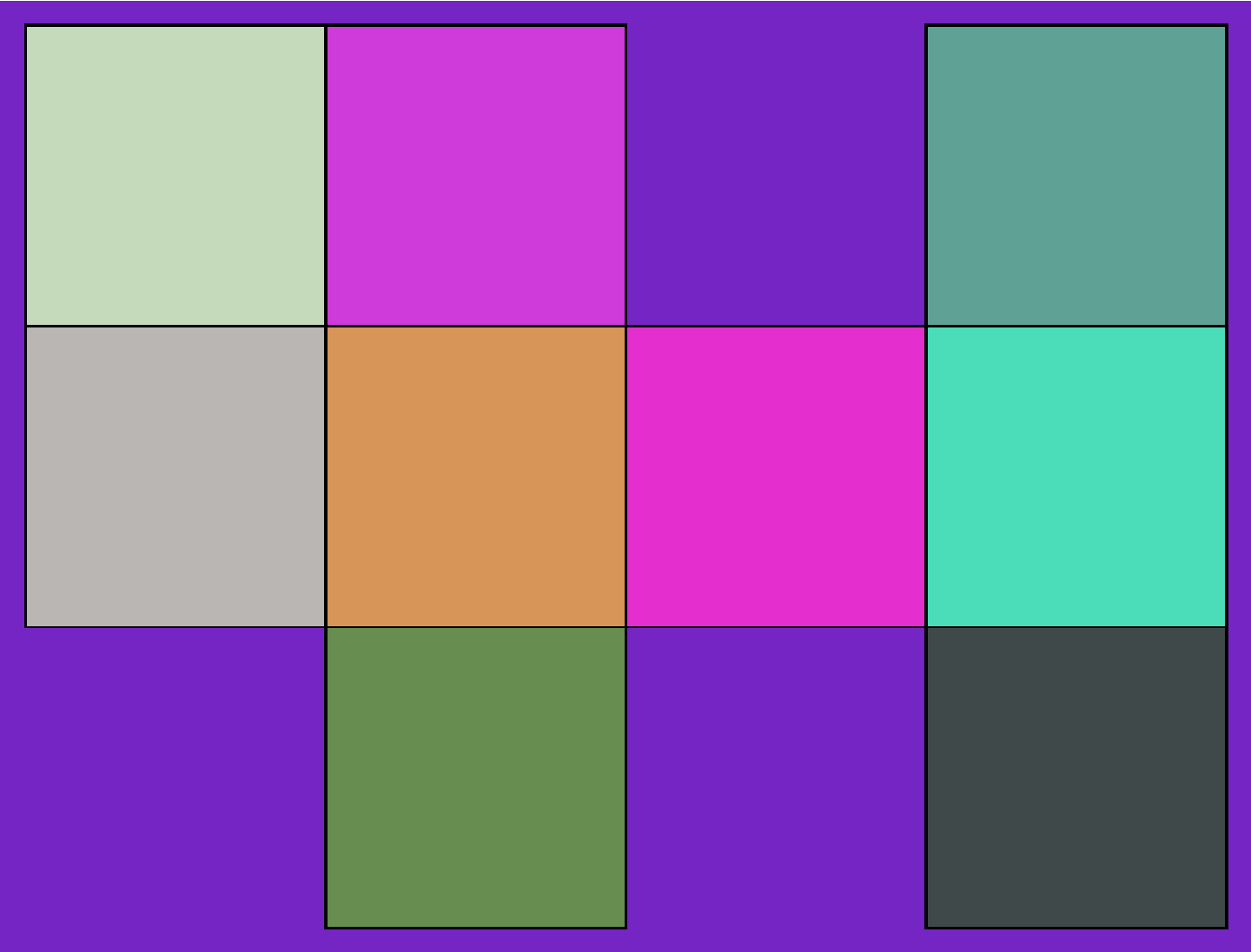
Visualization (each color roughly represents a polygon in the list above):

vis

Optimal solution for me

A solution that only uses geometry and graphics. In particular I want to avoid solutions that convert the graphics object to an image because I am unable to get Mathematica to use the right image size while preserving resolution.

Possible solutions

Geometric solution

One could maybe add a point very close to each line to turn the line to a triangle and then use RegionDifference of the RegionUnion of the modified lines (that are now triangles) with the BoundaryRegion of the RegionUnion of the lines (basically getting the complement region).

This solution is a bit ugly I do not really like it and have not tried it yet

Image solution

One could use ComponentMeasurements or // ImageMesh // ConnectedMeshComponents but this has the issue that it converts the graphics object to an image which changes the scale and then the scale of the rectangles are not the same as the original rectangles

Graph solution

One could convert the lines to points and lines using // Apply[RegionUnion] // DiscretizeRegion and then to a graph to search for cycles. I do not know how to do this at the moment but I might consider searching for ways to do that

$\endgroup$
15
  • $\begingroup$ Are the tiles always going to have 4 sides? In that case: Polygon /@ FindCycle[Graph[First /@ Apply[UndirectedEdge, lines, {2}]], {4}, All][[All, All, 1]] where lines is your list of lines. $\endgroup$
    – Domen
    Commented Oct 30, 2022 at 21:30
  • $\begingroup$ @Domen Nice (: . I told myself converting the lines to a graph would be complicated but it is a one liner. The example I gave was bad. In general the end points of the lines are not the the intersection with other lines but your solution worked by adding a bit more functions. Thank you. $\endgroup$ Commented Oct 30, 2022 at 22:08
  • $\begingroup$ The solution in the general case with random lines can be converted to the case you looked at with RegionUnion which adds the intersections. The full solution is then: lines // Apply[RegionUnion] // MeshPrimitives[#, 1] & // ReplaceAll[Line -> Identity] // MapApply[UndirectedEdge] // FindCycle[#, {4}, All] & // ReplaceAll[UndirectedEdge -> List] // Map[CrossingPolygon] $\endgroup$ Commented Oct 30, 2022 at 22:09
  • $\begingroup$ Many complicated things in Mathematica can be converted to funky one-liners :) I suggest you post your solution as a proper answer. $\endgroup$
    – Domen
    Commented Oct 30, 2022 at 22:10
  • $\begingroup$ I will add another example to make the generality of the question clearer. You can add your solution if you would like to. $\endgroup$ Commented Oct 30, 2022 at 22:11

2 Answers 2

1
$\begingroup$

I'm not entirely sure if your problem is fully defined, but here's one approach to start with, discretizing boundaries of finite components and showing them. CylindricalDecomposition is not limited to supporting only infinite lines, when it is provided with suitable exact definitions line segments are fine too.

With[{lines = 
       ArrayMesh[{{1, 1, 0, 1}, {1, 1, 1, 1}, {0, 1, 0, 1}}] // 
        MeshPrimitives[#, 1] &},
     RegionDifference[FullRegion[2], 
        RegionUnion[Rationalize[lines, 0]]] // 
       Refine[RegionMember[#, {x, y}], Element[x | y, Reals]] & // 
      CylindricalDecomposition[#, {x, y}, "Components"] &] // 
    Map[ImplicitRegion[#, {x, y}] &] // Select[BoundedRegionQ] // 
  Map[Quiet@*BoundaryDiscretizeRegion] // Show

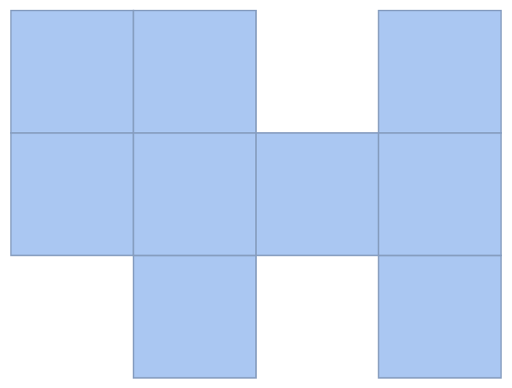
enter image description here

With[{lines = {Line[{{0., 92.2227}, {431.147, 750.}}], 
        Line[{{301.72, 750.}, {446.159, 0.}}], 
        Line[{{123.934, 750.}, {390.253, 0.}}], 
        Line[{{494., 432.03}, {0.470817, 750.}}], 
        Line[{{0., 388.081}, {494., 308.166}}]}},
     RegionDifference[FullRegion[2], 
        RegionUnion[Rationalize[lines, 0]]] // 
       Refine[RegionMember[#, {x, y}], Element[x | y, Reals]] & // 
      CylindricalDecomposition[#, {x, y}, "Components"] &] // 
    Map[ImplicitRegion[#, {x, y}] &] // Select[BoundedRegionQ] // 
  Map[Quiet@*BoundaryDiscretizeRegion] // Show

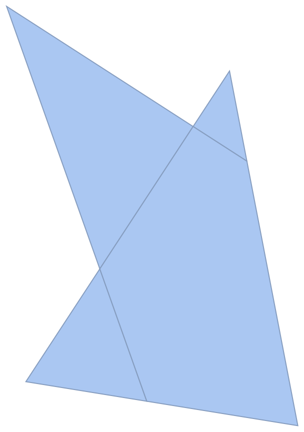
enter image description here

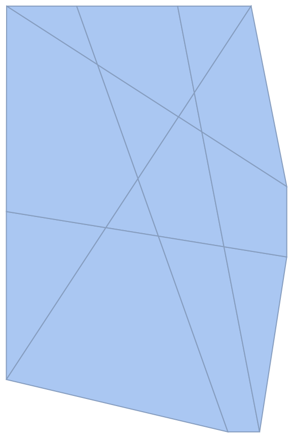
You can also replace FullRegion[2] with Quiet@BoundingRegion[RegionUnion[Rationalize[lines, 0]]] in the latter case (Quiet is for surpressing a strange, spurious error message) for getting tiles which would otherwise seem to be part of the unbounded exterior:

enter image description here

One might ask why this implicit bounding rectangle would be assumed. One could also consider, for instance, in this case a convex hull (like ConvexHullRegion[Join @@ Rationalize[lines[[All, 1]], 0]]):

enter image description here

$\endgroup$
4
  • $\begingroup$ Very nice. FullRegion here was a very neat idea and I am not even sure I knew about it. The complement with the bounding region or convex hull's introduce extra tiles that I did not want which was the problem I had with implementing your answer from the linked post when transforming the lines to infinite lines and taking the region difference with the bounding region as in the edit 1 code. $\endgroup$ Commented Dec 2, 2022 at 13:23
  • 1
    $\begingroup$ I also did not know that rationalizing the lines before with RegionUnion and RegionDifference leads to different behavior. Thank you for this answer that provides a lot of interesting information for future use. I will wait a day before I accept an answer. $\endgroup$ Commented Dec 2, 2022 at 13:26
  • 1
    $\begingroup$ I recently read about RegionConvert and tried replacing the RegionMember part of your code with RegionConvert[#, "Implicit"] & // Apply[Reduce[##, Reals] &] and it was 10 times faster. I don't know if you already tried that so I mentioned it. $\endgroup$ Commented Dec 3, 2022 at 8:28
  • $\begingroup$ @userrandrand I've tried it, but I didn't benchmark it... $\endgroup$
    – kirma
    Commented Dec 3, 2022 at 8:36
1
$\begingroup$

This is not a complete answer but in case no answer comes here is a partial solution for the case where the lines form a grid of squares:

lines // Apply[RegionUnion] // MeshPrimitives[#, 1] & // 
 ReplaceAll[Line -> Identity] // MapApply[UndirectedEdge] // 
 FindCycle[#, {4}, All] & // ReplaceAll[UndirectedEdge -> List] // 
 Map[CrossingPolygon]

Perhaps that would also work for a triangular lattice and other regular lattices but it is insufficient for a random lattice as the number of vertices vary. One could consider turning the lines to a graph and obtaining the faces of the graph using PlanarFaceList (version 13) but the polygons obtained were not the minimal (smallest) ones. Maybe using FindShortestPath would work using the same beginning and end vertex but that might be lengthy to apply for each vertex.

$\endgroup$

Your Answer

By clicking “Post Your Answer”, you agree to our terms of service and acknowledge you have read our privacy policy.

Not the answer you're looking for? Browse other questions tagged or ask your own question.