1
$\begingroup$

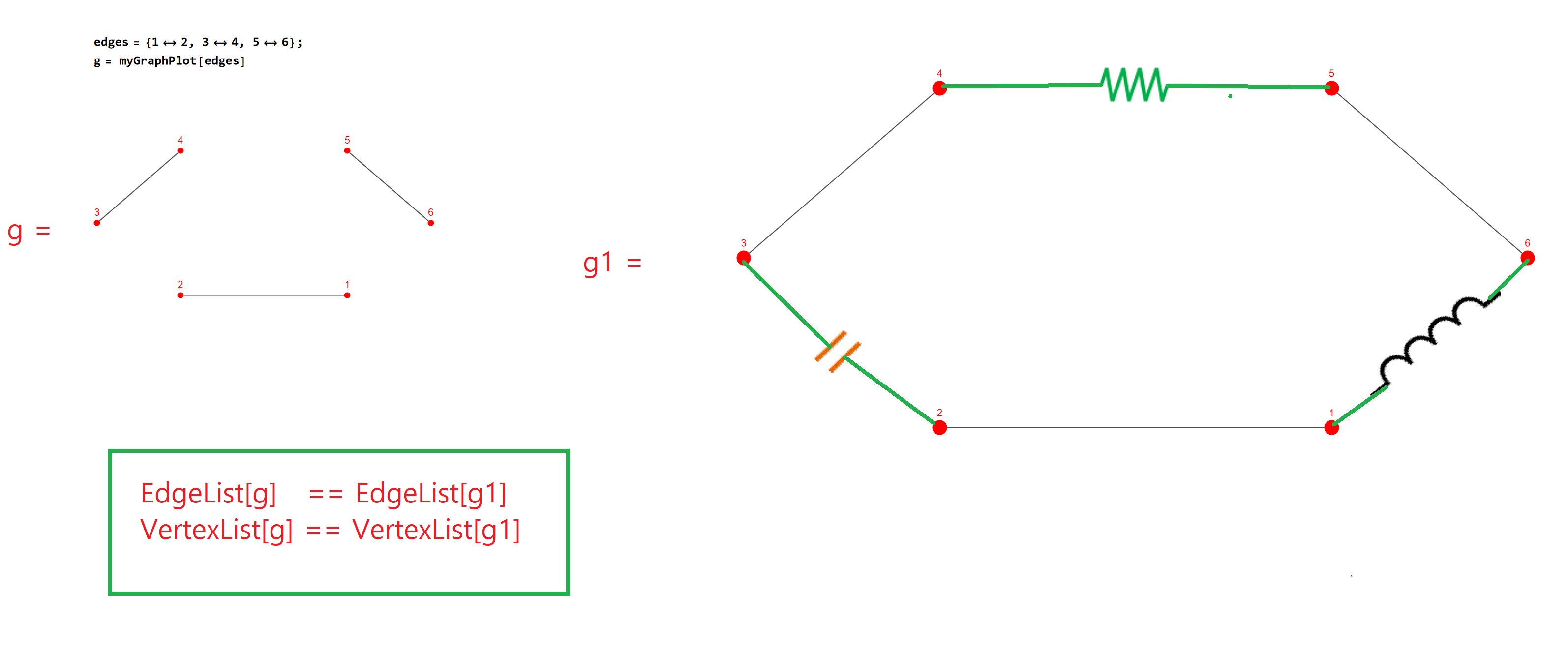
Is it possible to add some customized symbols between nodes (just for presentation) without affecting the graph?
This is an example where I added symbols of resistor, capacitor, and inductor between nodes.
However, the condition is that they're just like fake symbols and not affecting the graph at all.
So the two graphs still have the same vertex list and edge list:

EdgeList[g]   = EdgeList[g1]
VertexList[g] = VertexList[g1]

enter image description here

ellipseLayout[n_, {a_, b_}] := 
 Table[{a Cos[2 Pi/n u], -b Sin[2 Pi/n u]}, {u, 1, n}]; 
myGraphPlot[graph_] := 
 Graph[graph, VertexLabels -> Placed[Automatic, Above], 
  VertexLabelStyle -> Red, 
  VertexStyle -> Directive[Red, EdgeForm@None], EdgeStyle -> Black, 
  VertexCoordinates -> 
   ellipseLayout[Length@(VertexList[graph]), {2, 1}]];
edges = {1 <-> 2, 3 <-> 4, 5 <-> 6};
g = myGraphPlot[edges]
$\endgroup$
3
  • 1
    $\begingroup$ I'd suggest you look into EdgeShapeFunction (an option for Graph). $\endgroup$
    – lericr
    Commented Oct 26, 2022 at 17:52
  • $\begingroup$ @lericr Unfortunately it's only possible if there is an edge between two nodes. In my case, there is no edge between these two nodes. $\endgroup$
    – hana
    Commented Oct 27, 2022 at 14:01
  • 1
    $\begingroup$ Maybe Graph isn't the right construct for you. If you're just wanting to draw things between known points, then maybe just use graphics primitives. But if you want to stick with Graph, then just create a sort of "dual" graph that has the edges you need. You can merge the two graphs for presentation but can otherwise keep them separate and unchanged. $\endgroup$
    – lericr
    Commented Oct 27, 2022 at 14:08

1 Answer 1

1
$\begingroup$

You could set Prolog with graphic primitives:

Define symbols:

resistor[{a1_, a2_}] :=
 Block[{d, l, res, s, t},
  d = a2 - a1;
  l = Norm[d];
  s = a1 (1 - 2/5) + a2 2/5;
  t = a1 (1 - 3/5) + a2 3/5;
  res = Line[
    Table[{Norm[t - s] i /16, 1/(6 l) Sin[i Pi/2]}, {i, 0, 16}]];
  res = GeometricTransformation[res, 
    Composition[TranslationTransform[s], 
     RotationTransform[ArcTan @@ d]]];
  {Thick, Darker[Green], Line[{{a1, s}, {t, a2}}], res}
  ]

capacitor[{a1_, a2_}] :=
 Block[{d, l, nd, res, s, t},
  d = a2 - a1;
  l = Norm[d];
  s = a1 (1 - 4.5/9) + a2 4.5/9;
  t = a1 (1 - 5/9) + a2 5/9;
  nd = l/15 RotationTransform[Pi/2][Normalize[d]];
  res = Line[{{s + nd, s - nd}, {t + nd, t - nd}}];
  {Thick, Darker[Green], Line[{{a1, s}, {t, a2}}], Brown, res}
  ]

inductor[{a1_, a2_}] :=
 Block[{d, l, res, s, t, r},
  d = a2 - a1;
  l = Norm[d];
  s = a1 (1 - 1/5) + a2 1/5;
  t = a1 (1 - 4/5) + a2 4/5;
  r = (Norm[s - t]/4 ) 1/2;
  res = Table[Circle[{i + r, 0}, r, {0, Pi}], {i, 0, 6 r, 2 r }];
  res = GeometricTransformation[res, 
    Composition[TranslationTransform[s], 
     RotationTransform[ArcTan @@ d]]];
  {Thick, Darker[Green], Line[{{a1, s}, {t, a2}}], {Black, res}}
  ]

dc[{a1_, a2_}] := Block[{d, l, res, s, t, r}, d = a2 - a1;
  l = Norm[d];
  s = a1 (1 - 2/5) + a2 2/5;
  t = a1 (1 - 3/5) + a2 3/5;
  r = Norm[s - t]/2;
  res = {Circle[{r, 0}, r], Line[{{2 r/4, r/4 }, {2 r/4, -r/4}}], 
    Line[{{{r/3 + r, r/4 }, {r/3 + r, -r/4}}, {{r/3 + r - r/4, 
        0 }, {r/3 + r + r/4, 0}}}]};
  res = GeometricTransformation[res, 
    Composition[TranslationTransform[s], 
     RotationTransform[ArcTan @@ d]]];
  {Thick, Darker[Green], Line[{{a1, s}, {t, a2}}], res}]

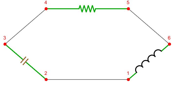
Set a new graph with Prolog:

coords = GraphEmbedding[g];
g1 = Graph[g, 
  Prolog -> {resistor[coords[[{4, 5}]]], capacitor[coords[[{2, 3}]]], 
    inductor[coords[[{1, 6}]]]}]
enter image description here

EdgeList[g] == EdgeList[g1]

True

$\endgroup$
9
  • $\begingroup$ Actually coloring is not required but very nice code. $\endgroup$
    – hana
    Commented Oct 27, 2022 at 15:02
  • $\begingroup$ Not asked in the question, do you have a code for a DC voltage source, that would be nice as well. Something like this. commons.wikimedia.org/wiki/File:Voltage_Source.svg $\endgroup$
    – hana
    Commented Oct 27, 2022 at 15:27
  • 1
    $\begingroup$ @hana I don't have the code.. but I just make one for dc.. $\endgroup$
    – halmir
    Commented Oct 27, 2022 at 15:48
  • 1
    $\begingroup$ @hana switch symbol could be done by modifying inductor code.. $\endgroup$
    – halmir
    Commented Oct 27, 2022 at 15:50
  • 1
    $\begingroup$ @hana you miss {} inside Line: Line[{{0,0}, {-r, 3r}}] $\endgroup$
    – halmir
    Commented Oct 27, 2022 at 16:54

Your Answer

By clicking “Post Your Answer”, you agree to our terms of service and acknowledge you have read our privacy policy.

Not the answer you're looking for? Browse other questions tagged or ask your own question.