7
$\begingroup$

The objective is to solve the 3D electric fields for the geometry below and generate the continuous function eField3D[x_,y_,z_]. The method I was planning on using was FEA to solve Laplace PDEs.

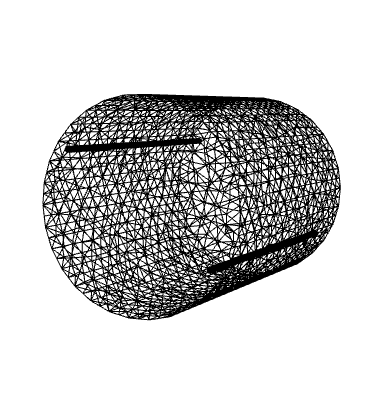
I have the following mesh generation code:

Needs["NDSolve`FEM`"]

cylinOffset = 0.032;
cylinLength = 0.100;
cylinRadius = 0.001;

shellLength = 0.100;
shellRadius = 0.0365;

cylinA = Cylinder[{{-cylinOffset, 0, -cylinLength /2}, 
         {-cylinOffset, 0, cylinLength /2}}, cylinRadius];
cylinB = Cylinder[{{cylinOffset, 0, -cylinLength /2}, 
         {cylinOffset, 0, cylinLength /2}}, cylinRadius];

shell = Cylinder[{{0, 0, -shellLength /2}, {0, 0, shellLength /2}}, shellRadius];

bmeshShell = ToBoundaryMesh[shell]["Wireframe"];
bmeshCylinA = ToBoundaryMesh[cylinA]["Wireframe"];
bmeshCylinB = ToBoundaryMesh[cylinB]["Wireframe"];

Show[bmeshShell, bmeshCylinA, bmeshCylinB]

enter image description here

I'm quite confused on how to progress further. The following is an attempt to setup the boundary conditions of voltage potential and region where the equations should be evaluated, but I'm far away from a solution. Guidance would be very much appreciated.

reg = {bmeshShell, bmeshCylinA, bmeshCylinB};
sol = NDSolveValue[{Inactive[Laplacian][u[x, y, z], {x, y, z}] == 0, 
      DirichletCondition[bmeshShell == 0, 
      bmeshCylinA == bmeshCylinB == 30000]}, 
      u, {x, y, z} \[Element] reg];
$\endgroup$
4
  • $\begingroup$ How do your boundary conditions work? Are you saying you want the function u[x, y, z] to be zero at the bmeshShell boundary and 30000 at the other two boundaries? I think the syntax of your DirichletCondition is not correct $\endgroup$
    – Jason B.
    Commented Jun 25, 2016 at 18:08
  • $\begingroup$ Yes. Zero potential at the shell and 30 000 at each cylinder. I'm sure DirichletCondition is wrong and the region isn't setup correctly either. I'm working on figuring out the region definition now. $\endgroup$
    – Young
    Commented Jun 25, 2016 at 18:14
  • 1
    $\begingroup$ I think it should be more like this, sol = NDSolveValue[{Inactive[Laplacian][u[x, y, z], {x, y, z}] == 0, DirichletCondition[u[x, y, z] == 0, bmeshShell], DirichletCondition[u[x, y, z] == 30000, bmeshCylinA], DirichletCondition[u[x, y, z] == 30000, bmeshCylinB]}, u, {x, y, z} \[Element] shell] but I still don't get it to give me an answer. Maybe we can get @user21 to take a look at this, he's the expert $\endgroup$
    – Jason B.
    Commented Jun 25, 2016 at 18:18
  • 1
    $\begingroup$ Try a 2D example first and the extend that to 3D. Also, reg = {bmeshShell, bmeshCylinA, bmeshCylinB} is not how it works. I think I'd start expressing the region as an ImplicitRegion. $\endgroup$
    – user21
    Commented Jun 27, 2016 at 3:26

1 Answer 1

6
$\begingroup$

Using user21's advice, I built the 2D model of the system then expanded it to 3D.

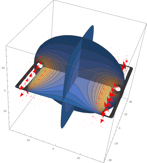
Here is the general 3D solution:

ClearAll["Global`*"]
Needs["NDSolve`FEM`"];

cylinLength = 73.0;
cylinRadius =  1.0;
cylinBuffer =  5.0;
cylinOffset = 32.0;
shellRadius = 36.5;

cylinVoltage = 30000;

shell = Cylinder[{{0, 0, -cylinLength/2}, {0, 0, cylinLength/2}}, shellRadius];
cylin = RegionUnion[
   Cylinder[{{-cylinOffset, 0, -cylinLength/2}, {-cylinOffset, 0, 
      cylinLength/2}}, cylinRadius],
   Cylinder[{{cylinOffset, 0, -cylinLength/2}, {cylinOffset, 0, 
      cylinLength/2}}, cylinRadius]];

region = RegionDifference[shell, cylin];

solMV = NDSolveValue[
  {D[u[x, y, z], x, x] + D[u[x, y, z], y, y] + D[u[x, y, z], z, z] == 0,
    DirichletCondition[u[x, y, z] == 0, z^2 == (cylinLength/2)^2],
    DirichletCondition[u[x, y, z] == 0, 
     x^2 + y^2 == shellRadius^2 && z^2 < (cylinLength/2)^2 + (cylinBuffer)^2],
    DirichletCondition[
     u[x, y, z] == 
      cylinVoltage, (x + cylinOffset)^2 + y^2 == cylinRadius^2 && 
      z^2 < (cylinLength/2)^2 + (cylinBuffer)^2],
    DirichletCondition[
     u[x, y, z] == 
      cylinVoltage, (x - cylinOffset)^2 + y^2 == cylinRadius^2 && 
      z^2 < (cylinLength/2)^2 + (cylinBuffer)^2]},
   u, {x, y, z} ∈ region, InterpolationOrder -> All, 
   Method -> {"FiniteElement", "MeshOptions" -> {"MaxCellMeasure" -> 1}}];

solME[x_, y_, z_] = -Grad[solMV[x, y, z], {x, y, z}];

Show[
 SliceContourPlot3D[solMV[x, y, z], 
  "CenterPlanes", {x, y, z} ∈ sol["ElementMesh"], Contours -> 20, 
  PlotRange -> All, PlotLegends -> Automatic],
 VectorPlot3D[
  solME[x, y, z], {x, -shellRadius, shellRadius}, {y, -shellRadius, 
   shellRadius}, {z, -cylinLength/2, cylinLength/2}, 
  VectorStyle -> Red, VectorPoints -> Fine]
 ]

enter image description here

Improvements welcome.

$\endgroup$
2
  • $\begingroup$ When I tried the code above, it threw numerous NDSolveValue errors. Is there a missing initialization or code in the example above? $\endgroup$ Commented Feb 18, 2019 at 11:55
  • $\begingroup$ The primary errors are ToElementMesh::femtemnbb and NDSolveValue::bcnoop. ToElementMesh::femtemnbb is generated when no numeric bounds can be computed for a region. For the code above, there are no places on the boundaries that satisfy the Dirichlet conditions. $\endgroup$ Commented Feb 18, 2019 at 12:16

Your Answer

By clicking “Post Your Answer”, you agree to our terms of service and acknowledge you have read our privacy policy.

Not the answer you're looking for? Browse other questions tagged or ask your own question.