As I showed in this answer 225595, the appropriate momentum flux variable is traction or stress vector and not the stress tensor. Therefore, the normal must be dotted with the stress tensor to obtain the traction vector:
$${{\mathbf{T}}^{(\hat {\mathbf{n}})}} = \hat {\mathbf{n}} \cdot {\mathbf{\sigma }}$$
For scalar properties, such as energy and mass, the NeumannValue can simplify the formulation of a PDE on a complex geometry because we do not need to know the surface normals. We simply need to know whether the flux is into or out of the domain as shown in the following diagram.
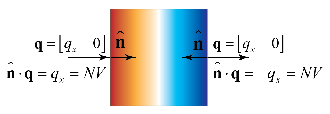
Unfortunately, we require knowledge of the surface normal when considering vector properties such as momentum, so we lose that advantage with the NeumannValue. Just remember that we are using traction versus stress to define the NeumannValue.
For the following, I am going to reduce the dimension to a 2D problem, just to save some memory and to simplify mesh construction. In 2D, we can represent the principal stresses with the follow diagram.
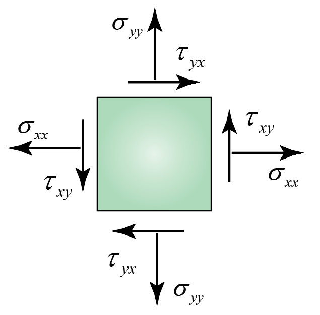
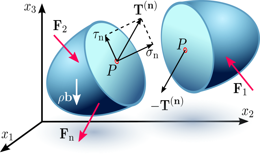
The traction vector is the vector sum of the principal stresses on a plane as shown in the figure taken from the Hooke's Law Wiki Article.
Construction of Meshes
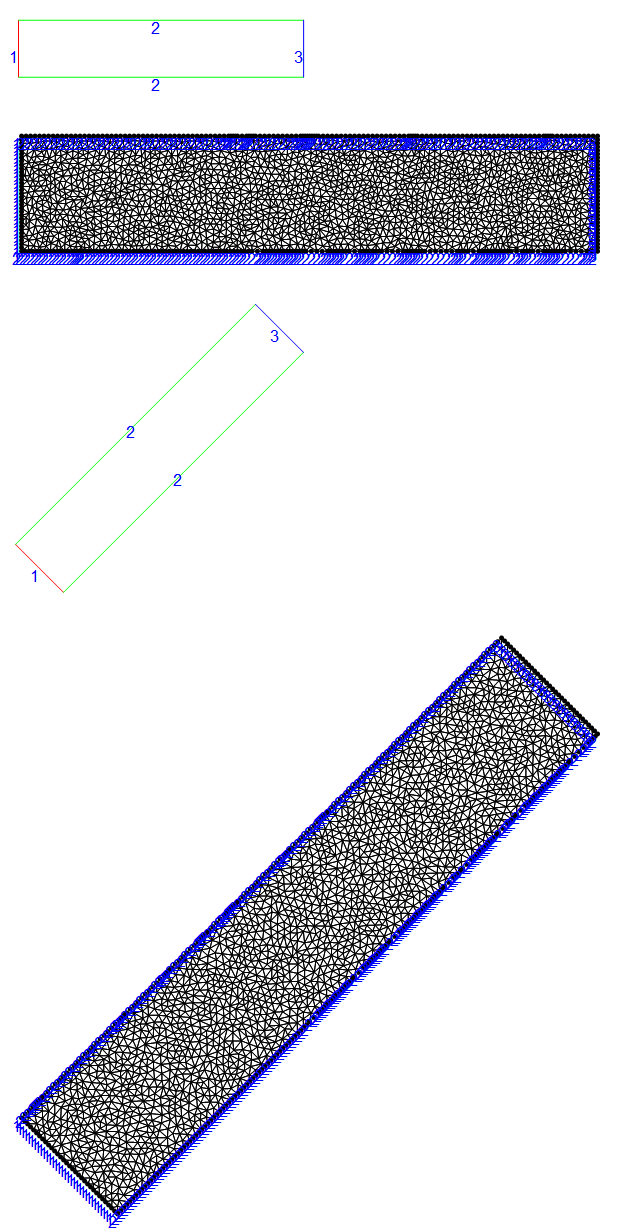
I will use ToBoundaryElementMesh so I can use ElementMarkers to refer to boundaries. Let's create a normal rectangular mesh and one that is rotated $45^{\circ}$
Needs["NDSolve`FEM`"]
(* Function to create bmesh rectangle with markers *)
bmeshrect[left_, bottom_, length_, height_, leftedge_, bottomedge_,
  rightedge_, topedge_, angle_ : 0] :=
 With[{right = left + length, top = bottom + height},
  ToBoundaryMesh[
   "Coordinates" -> RotationTransform[angle, First[#]] /@ # &@{{left,
      bottom}(*1*), {right, bottom}(*2*), {right, top}(*3*), {left,
      top}(*4*)},
   "BoundaryElements" -> {LineElement[{{1, 2}(*bottom edge*)(*1*), {4,
         1}(*left edge*)(*2*), {2, 3}(*3*)(*right edge*), {3,
        4}(*4*)(*top edge*)}, {bottomedge, leftedge, rightedge,
       topedge}]}]]
(* Unrotated *)
bmesh = bmeshrect[0, 0, 5, 1, 1, 2, 3, 2, 0 \[Degree]];
bmesh["Wireframe"["MeshElementMarkerStyle" -> Blue,
  "MeshElementStyle" -> {Red, Green, Blue}, ImageSize -> Small]]
mesh = ToElementMesh[bmesh, MaxCellMeasure -> {"Length" -> .1}];
Show[mesh["Wireframe"],
 mesh["Wireframe"["MeshElement" -> "PointElements",
   "MeshElementMarkerStyle" -> Blue]]]
(* Rotated by 45 deg *)
bmesh = bmeshrect[0, 0, 5, 1, 1, 2, 3, 2, 45 \[Degree]];
bmesh["Wireframe"["MeshElementMarkerStyle" -> Blue,
  "MeshElementStyle" -> {Red, Green, Blue}, ImageSize -> Small]]
mesh45 = ToElementMesh[bmesh, MaxCellMeasure -> {"Length" -> .1}];
Show[mesh45["Wireframe"],
 mesh45["Wireframe"["MeshElement" -> "PointElements",
   "MeshElementMarkerStyle" -> Blue]]]
Set up Plane Stress Operator
(* set material parameters *)
materialParameters = {Y -> 10^3, ν -> 33/100};
(* set up factor matrix to be used in subsequent stress calcs *)
pfac = Y/(1 - ν^2)*{{1, ν, 0}, {ν, 1, 0}, {0,
     0, (1 - ν)/2}};
fac = pfac /. materialParameters;
ClearAll[ν, Y]
parmop = {Inactive[
      Div][({{0, -((Y ν)/(1 - ν^2))}, {-((Y (1 - ν))/(
          2 (1 - ν^2))), 0}}.Inactive[Grad][v[x, y], {x, y}]), {x,
       y}] + Inactive[
      Div][({{-(Y/(1 - ν^2)),
         0}, {0, -((Y (1 - ν))/(2 (1 - ν^2)))}}.Inactive[
         Grad][u[x, y], {x, y}]), {x, y}],
   Inactive[
      Div][({{0, -((Y (1 - ν))/(2 (1 - ν^2)))}, {-((Y ν)/(
          1 - ν^2)), 0}}.Inactive[Grad][u[x, y], {x, y}]), {x,
      y}] + Inactive[
      Div][({{-((Y (1 - ν))/(2 (1 - ν^2))),
         0}, {0, -(Y/(1 - ν^2))}}.Inactive[Grad][
        v[x, y], {x, y}]), {x, y}]};
(* pde plane stress operator *)
op = parmop /. materialParameters;
Solve PDE System for Unrotated and Rotated Meshes
Fix Left Boundary
(* Fix left boundary *)
dcx = DirichletCondition[u[x, y] == 0., ElementMarker == 1];
dcy = DirichletCondition[v[x, y] == 0., ElementMarker == 1];
(* Create parametric functions of both meshes *)
pfun = ParametricNDSolveValue[{op == {NeumannValue[sx,
       ElementMarker == 3], NeumannValue[sy, ElementMarker == 3]},
    dcx, dcy}, {u, v}, {x, y} \[Element] mesh, {sx, sy}];
pfun45 = ParametricNDSolveValue[{op == {NeumannValue[sx,
       ElementMarker == 3], NeumannValue[sy, ElementMarker == 3]},
    dcx, dcy}, {u, v}, {x, y} \[Element] mesh45, {sx, sy}];
(* Set normal, stress, and traction *)
n = {1, 0};
stress = {{0, 1}, {1, 0}};
traction = n.stress;
(* Solve and display unrotated mesh *)
{ufun, vfun} = pfun @@ traction;
msh = ufun["ElementMesh"];
Show[{msh["Wireframe"["MeshElement" -> "BoundaryElements"]],
  ElementMeshDeformation[msh, {ufun, vfun}][
   "Wireframe"[
    "ElementMeshDirective" -> Directive[EdgeForm[Red], FaceForm[]]]]}]
(* Solve and display rotated mesh *)
{ufun, vfun} = pfun45 @@ RotationTransform[45 \[Degree]][traction];
msh = ufun["ElementMesh"];
Show[{msh["Wireframe"["MeshElement" -> "BoundaryElements"]],
  ElementMeshDeformation[msh, {ufun, vfun}][
   "Wireframe"[
    "ElementMeshDirective" -> Directive[EdgeForm[Red], FaceForm[]]]]}]
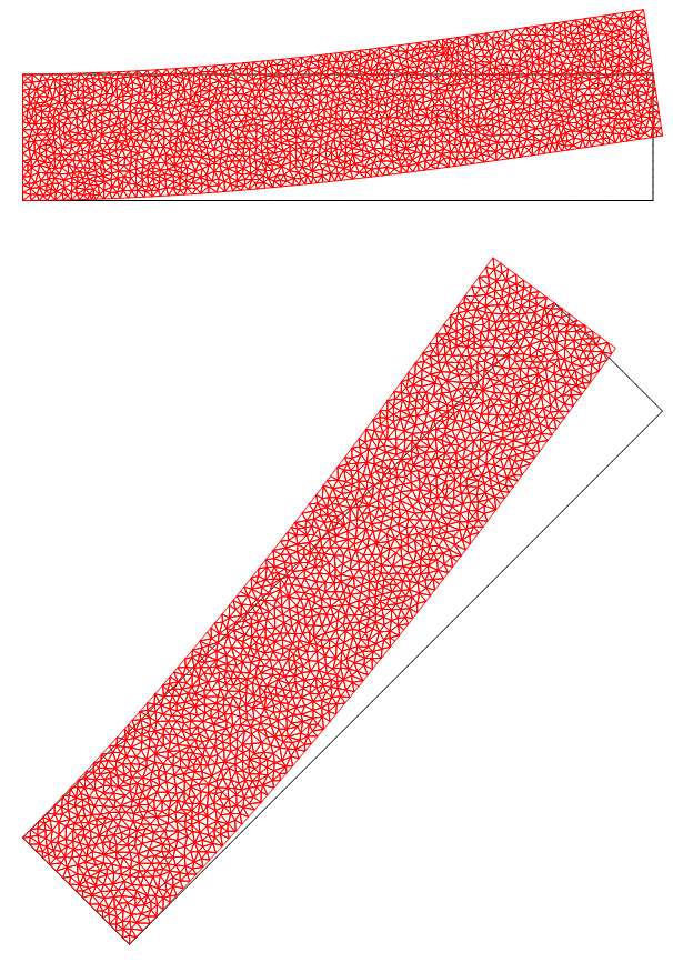
Fix Right Boundary
(* Fix right boundary *)
dcx = DirichletCondition[u[x, y] == 0., ElementMarker == 3];
dcy = DirichletCondition[v[x, y] == 0., ElementMarker == 3];
(* Create parametric functions of both meshes *)
pfun = ParametricNDSolveValue[{op == {NeumannValue[sx,
       ElementMarker == 1], NeumannValue[sy, ElementMarker == 1]},
    dcx, dcy}, {u, v}, {x, y} \[Element] mesh, {sx, sy}];
pfun45 = ParametricNDSolveValue[{op == {NeumannValue[sx,
       ElementMarker == 1], NeumannValue[sy, ElementMarker == 1]},
    dcx, dcy}, {u, v}, {x, y} \[Element] mesh45, {sx, sy}];
(* Set normal, stress, and traction *)
n = {-1, 0};
stress = {{0, 1}, {1, 0}};
traction = n.stress;
(* Solve and display unrotated mesh *)
{ufun, vfun} = pfun @@ traction;
msh = ufun["ElementMesh"];
Show[{msh["Wireframe"["MeshElement" -> "BoundaryElements"]],
  ElementMeshDeformation[msh, {ufun, vfun}][
   "Wireframe"[
    "ElementMeshDirective" -> Directive[EdgeForm[Red], FaceForm[]]]]}]
(* Solve and display rotated mesh *)
{ufun, vfun} = pfun45 @@ RotationTransform[45 \[Degree]][traction];
msh = ufun["ElementMesh"];
Show[{msh["Wireframe"["MeshElement" -> "BoundaryElements"]],
  ElementMeshDeformation[msh, {ufun, vfun}][
   "Wireframe"[
    "ElementMeshDirective" -> Directive[EdgeForm[Red], FaceForm[]]]]}]
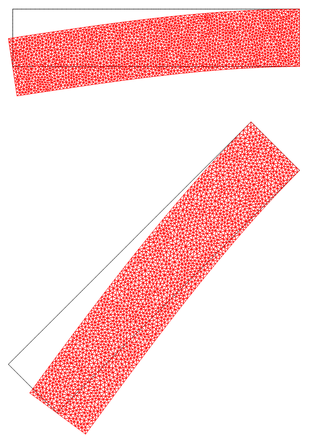
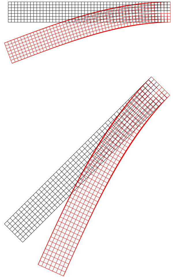
These results are consistent with the principal stress diagram and what I believe Hugh expected. I also showed that without too much effort, we can apply the approach to a rotated mesh. The key is to recognize that we need to convert stress into a traction vector.
Extension to 3D
For completeness, I will extend this methodology to the 3D case.
Create 3D Meshes
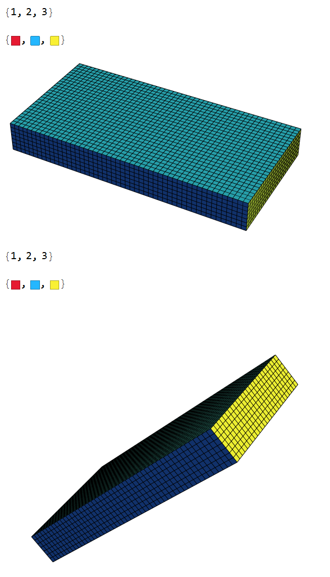
In 2D, Boundary Elements for NeumannValue and Point Elements for DirichletCondition are handled automatically if one first creates a bmesh with ToBoundaryMesh. In 3D, I did not find an analogous approach. However, one can use PointMarkerFunction and BoundaryMarkerFunction to assign nodal and elemental markers. The following workflow will create a mesh where we mark the left and right face:
(* Create 3D Mesh *)
(* 3D Parameters *)
Len = 1;  (*length *)
ht = 0.125; (* height *)
wd = 0.5; (* width *)
(* Material Parameters *)
materialParameters = {Y -> 10^3, \[Nu] -> 33/100};
ss = 1;(*Shear stress on beam*)
reg = Cuboid[{0, -wd/2, 0}, {Len, wd/2, ht}];
{{xmn, xmx}, {ymn, ymx}, {zmn, zmx}} = RegionBounds@reg;
(* Point Marker Function for Dirichlet Conditions *)
pointMarkerFunction =
  Compile[{{coords, _Real, 2}, {pMarker, _Integer, 1}},
   Block[{x = #[[1]], y = #[[2]], z = #[[3]], epsilon},
      epsilon = 10^-6.;
      Which[
       Abs[x - xmn] <= epsilon, 1,
       Abs[x - xmx] <= epsilon, 3,
       Abs[y - ymn] <= epsilon, 2,
       Abs[y - ymx] <= epsilon, 2,
       Abs[z - zmn] <= epsilon, 2,
       Abs[z - zmx] <= epsilon, 2,
       True, 0
       ]] & /@ coords];
(* Boundary Marker Function for NeumannValues *)
boundaryMarkerFunction =
  Compile[{{boundaryElementCoords, _Real,
     3}, {boundaryElementPointMarkers, _Integer, 2}}, Which[
      Union[#] == {1}, 1,
      Union[#] == {3}, 3,
      True, 2 ] & /@ boundaryElementPointMarkers];
mesh3D = ToElementMesh[reg,
   "PointMarkerFunction" -> pointMarkerFunction,
   "BoundaryMarkerFunction" -> boundaryMarkerFunction];
groups = mesh3D["BoundaryElementMarkerUnion"]
temp = Most[Range[0, 1, 1/(Length[groups])]];
colors = ColorData["BrightBands"][#] & /@ temp
mesh3D["Wireframe"["MeshElementStyle" -> FaceForm /@ colors]]
(* Rotate Mesh 45 deg *)
mesh3D45 =
  ToElementMesh[
   "Coordinates" ->
      RotationTransform[-Pi/4, {0, 1, 0}, First[#]] /@ # &@
    mesh3D["Coordinates"], "MeshElements" -> mesh3D["MeshElements"],
   "BoundaryElements" -> mesh3D["BoundaryElements"],
   "PointElements" -> mesh3D["PointElements"]];
groups = mesh3D45["BoundaryElementMarkerUnion"]
temp = Most[Range[0, 1, 1/(Length[groups])]];
colors = ColorData["BrightBands"][#] & /@ temp
mesh3D45["Wireframe"["MeshElementStyle" -> FaceForm /@ colors]]
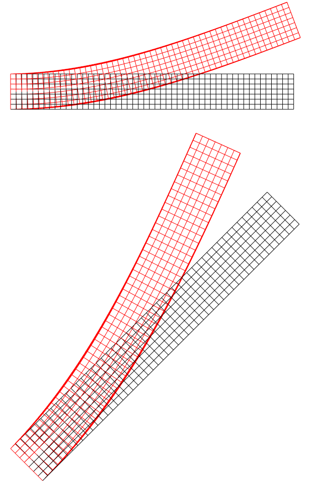
Fix Left Edge and Positive $\sigma_{xz}$ on Right Edge
(* Hugh's 3D Stress Operator *)
ClearAll[stressOperator, stressOperatorDynamic, u, v, w, x, y, z, Y, \
\

  ν]; stressOperator[{Y_, ν_}] := {Inactive[

     Div][{{0, 0, -((Y*ν)/((1 - 2*ν)*(1 + ν)))}, {0, 0,
              0}, {-Y/(2*(1 + ν)), 0, 0}}.Inactive[Grad][
            w[x, y, z], {x, y, z}], {x, y, z}] +
      Inactive[
          Div][{{0, -((Y*ν)/((1 - 2*ν)*(1 + ν))),
              0}, {-Y/(2*(1 + ν)), 0, 0}, {0, 0, 0}}.Inactive[
       Grad][
            v[x, y, z], {x, y, z}], {x, y, z}] +
      Inactive[
          Div][{{-((Y*(1 - ν))/((1 - 2*ν)*(1 + ν))), 0,
              0}, {0, -Y/(2*(1 + ν)), 0}, {0,
              0, -Y/(2*(1 + ν))}}.Inactive[Grad][
            u[x, y, z], {x, y, z}], {x, y, z}],
    Inactive[Div][{{0, 0, 0}, {0,
              0, -((Y*ν)/((1 -

              2*ν)*(1 + ν)))}, {0, -Y/(2*(1 + ν)),
              0}}.Inactive[Grad][w[x, y, z], {x, y, z}], {x, y, z}] +
      Inactive[
          Div][{{0, -Y/(2*(1 + ν)),
              0}, {-((Y*ν)/((1 - 2*ν)*(1 + ν))), 0,
       0}, {0, 0,
              0}}.Inactive[Grad][u[x, y, z], {x, y, z}], {x, y, z}] +
      Inactive[
          Div][{{-Y/(2*(1 + ν)), 0,
              0}, {0, -((Y*(1 - ν))/((1 - 2*ν)*(1 + ν))),
       0}, {0,
               0, -Y/(2*(1 + ν))}}.Inactive[Grad][
            v[x, y, z], {x, y, z}], {x, y, z}],
    Inactive[Div][{{0, 0, 0}, {0,
              0, -Y/(2*(1 + ν))}, {0, -((Y*ν)/((1 -
                            2*ν)*(1 + ν))), 0}}.Inactive[Grad][
            v[x, y, z], {x, y, z}], {x, y, z}] +
      Inactive[
          Div][{{0, 0, -Y/(2*(1 + ν))}, {0, 0,
              0}, {-((Y*ν)/((1 - 2*ν)*(1 + ν))), 0,
       0}}.Inactive[
              Grad][u[x, y, z], {x, y, z}], {x, y, z}] +
      Inactive[

     Div][{{-Y/(2*(1 + ν)), 0, 0}, {0, -Y/(2*(1 + ν)), 0}, {0,

       0, -((Y*(1 - ν))/((1 - 2*ν)*(1 + ν)))}}.Inactive[
              Grad][w[x, y, z], {x, y, z}], {x, y, z}]};
(* Fix Left Edge/NeumannValue on Right Edge *)
parmop = stressOperator[{Y, ν}];
op = parmop /. materialParameters;
dcx = DirichletCondition[u[x, y, z] == 0., ElementMarker == 1];
dcy = DirichletCondition[v[x, y, z] == 0., ElementMarker == 1];
dcz = DirichletCondition[w[x, y, z] == 0., ElementMarker == 1];
nv = {NeumannValue[sx, ElementMarker == 3],
   NeumannValue[sy, ElementMarker == 3],
   NeumannValue[sz, ElementMarker == 3]};
pfun = ParametricNDSolveValue[{op == nv, dcx, dcy, dcz}, {u, v,
    w}, {x, y, z} ∈ mesh3D, {sx, sy, sz}];
pfun45 = ParametricNDSolveValue[{op == nv, dcx, dcy, dcz}, {u, v,
    w}, {x, y, z} ∈ mesh3D45, {sx, sy, sz}];
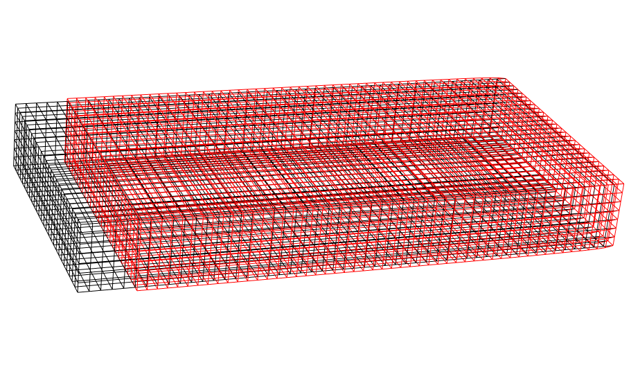
Now solve and view solutions of unrotated and rotated meshes:
(* Set normal, z-stress, and traction for right edge *)
n = {1, 0, 0};
stress = {{0, 0, 1}, {0, 0, 0}, {1, 0, 0}};
traction = n.stress;
(* Solve and display unrotated mesh *)
{ufun, vfun, wfun} = pfun @@ traction;
msh = ufun["ElementMesh"];
Show[{msh["Wireframe"["MeshElement" -> "BoundaryElements"]],
  ElementMeshDeformation[msh, {ufun, vfun, wfun}][
   "Wireframe"[
    "ElementMeshDirective" -> Directive[EdgeForm[Red], FaceForm[]]]]},
  ViewPoint -> {0, -Infinity, 0}]
(* Solve and display rotated mesh *)
{ufun, vfun, wfun} =
  pfun45 @@ RotationTransform[-Pi/4, {0, 1, 0}][traction];
msh45 = ufun["ElementMesh"];
Show[{msh45["Wireframe"["MeshElement" -> "BoundaryElements"]],
  ElementMeshDeformation[msh45, {ufun, vfun, wfun}][
   "Wireframe"[
    "ElementMeshDirective" -> Directive[EdgeForm[Red], FaceForm[]]]]},
  ViewPoint -> {0, -Infinity, 0}]
Fix Right Edge and Positive $\sigma_{xz}$ on Left Edge
(* Fix Left Edge/NeumannValue on Right Edge *)
dcx = DirichletCondition[u[x, y, z] == 0., ElementMarker == 3];
dcy = DirichletCondition[v[x, y, z] == 0., ElementMarker == 3];
dcz = DirichletCondition[w[x, y, z] == 0., ElementMarker == 3];
nv = {NeumannValue[sx, ElementMarker == 1],
   NeumannValue[sy, ElementMarker == 1],
   NeumannValue[sz, ElementMarker == 1]};
pfun = ParametricNDSolveValue[{op == nv, dcx, dcy, dcz}, {u, v,
    w}, {x, y, z} \[Element] mesh3D, {sx, sy, sz}];
pfun45 = ParametricNDSolveValue[{op == nv, dcx, dcy, dcz}, {u, v,
    w}, {x, y, z} \[Element] mesh3D45, {sx, sy, sz}];
(* Set normal, z-stress, and traction for left edge *)
n = {-1, 0, 0};
stress = {{0, 0, 1}, {0, 0, 0}, {1, 0, 0}};
traction = n.stress;
(* Solve and display unrotated mesh *)
{ufun, vfun, wfun} = pfun @@ traction;
msh = ufun["ElementMesh"];
Show[{msh["Wireframe"["MeshElement" -> "BoundaryElements"]],
  ElementMeshDeformation[msh, {ufun, vfun, wfun}][
   "Wireframe"[
    "ElementMeshDirective" -> Directive[EdgeForm[Red], FaceForm[]]]]},
  ViewPoint -> {0, -Infinity, 0}]
(* Solve and display rotated mesh *)
{ufun, vfun, wfun} =
  pfun45 @@ RotationTransform[-Pi/4, {0, 1, 0}][traction];
msh45 = ufun["ElementMesh"];
Show[{msh45["Wireframe"["MeshElement" -> "BoundaryElements"]],
  ElementMeshDeformation[msh45, {ufun, vfun, wfun}][
   "Wireframe"[
    "ElementMeshDirective" -> Directive[EdgeForm[Red], FaceForm[]]]]},
  ViewPoint -> {0, -Infinity, 0}]
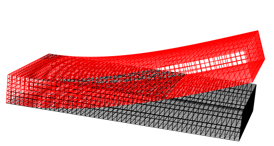
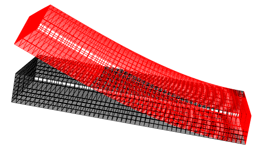
The approach works for 3D as well, but setting up boundary markers is more involved.



NeumannValuedefinition. I'd need to think about that.... $\endgroup$NeumannValueto the use ofDerivativeon the boundary. I think I'd start a more mathematical description of what your are seeing from that one. $\endgroup$