EDIT2 the answers here (How to compute intersections of circles on a lattice) seem like they could help or solve the problem.
EDIT: I saw this question about finding regions between lines before I asked. The ImageMesh solution can work but there is some re-scaling involved because the scale is not conserved when moving from a graphics object to an image. Other solutions explicitly or implicitly rely on the existence of infinite lines. If it is safe to extend the lines to infinite lines then one can obtain the desired domain using :
RegionDifference[BoundingRegion@RegionUnion@lines, RegionUnion@ReplaceAll[Line->InfiniteLine]@lines]
That is not the case of the first example below as that would add extra squares by "completing" the figure within the bounding region.
That said if one is interested in the scenario where the shape is regular and it is safe to extend the lines within the bounding region then one can also use the cylindrical decomposition. It might be necessary to rationalize the equations before applying the decomposition (I did not and got an error). For example like this :
RegionDifference[BoundingRegion@RegionUnion@lines,
    RegionUnion@ReplaceAll[Line -> InfiniteLine]@lines] //
   Refine[RegionMember[#, {x, y}], Element[x | y, Reals]] & //
  Rationalize[#, 0] &  //
 CylindricalDecomposition[#, {x, y}, "Components"] &
Other solutions use HalfSpace this also relies on the existence of an infinite line.
The method using graphs in that question might work but I did not try long enough to understand it.
I would like the following input/output:
Input:
A list of geometric lines
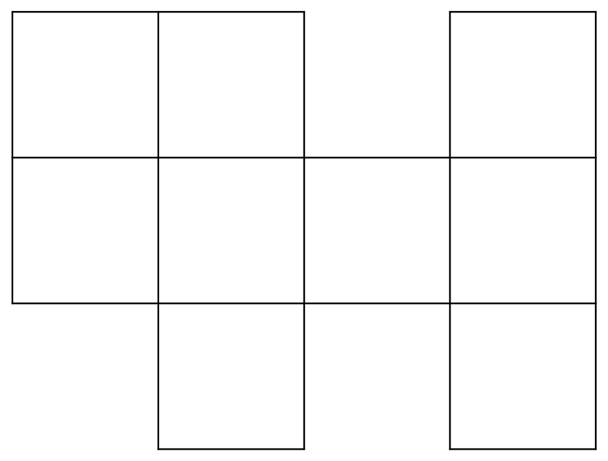
Example 1:
ArrayMesh[{{1, 1, 0, 1}, {1, 1, 1, 1}, {0, 1, 0, 1}}] //
MeshPrimitives[#, 1] &

{Line[{{1.,2.},{1.,3.}}],Line[{{1.,3.},{0.,3.}}],Line[{{0.,3.},{0.,2.}}],Line[{{0.,2.},{1.,2.}}],Line[{{2.,2.},{2.,3.}}],Line[{{2.,3.},{1.,3.}}],Line[{{1.,2.},{2.,2.}}],Line[{{4.,2.},{4.,3.}}],Line[{{4.,3.},{3.,3.}}],Line[{{3.,3.},{3.,2.}}],Line[{{3.,2.},{4.,2.}}],Line[{{1.,1.},{1.,2.}}],Line[{{0.,2.},{0.,1.}}],Line[{{0.,1.},{1.,1.}}],Line[{{2.,1.},{2.,2.}}],Line[{{1.,1.},{2.,1.}}],Line[{{3.,1.},{3.,2.}}],Line[{{3.,2.},{2.,2.}}],Line[{{2.,1.},{3.,1.}}],Line[{{4.,1.},{4.,2.}}],Line[{{3.,1.},{4.,1.}}],Line[{{2.,0.},{2.,1.}}],Line[{{1.,1.},{1.,0.}}],Line[{{1.,0.},{2.,0.}}],Line[{{4.,0.},{4.,1.}}],Line[{{3.,1.},{3.,0.}}],Line[{{3.,0.},{4.,0.}}]}
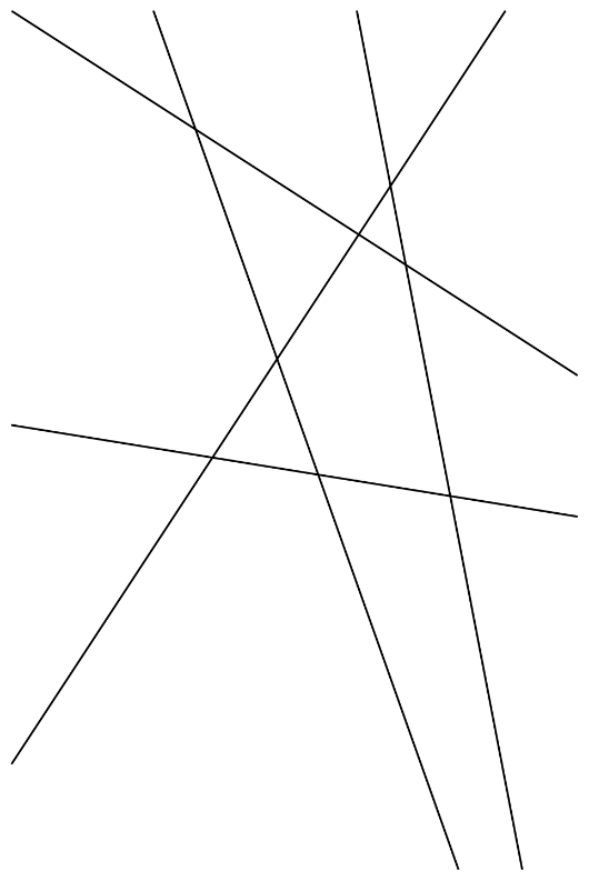
Example 2
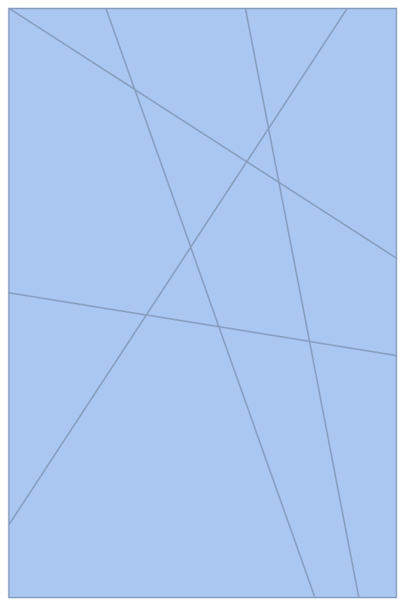
{Line[{{0., 92.2227}, {431.147, 750.}}],
 Line[{{301.72, 750.}, {446.159, 0.}}],
 Line[{{123.934, 750.}, {390.253, 0.}}],
 Line[{{494., 432.03}, {0.470817, 750.}}],
 Line[{{0., 388.081}, {494., 308.166}}]}
Output:
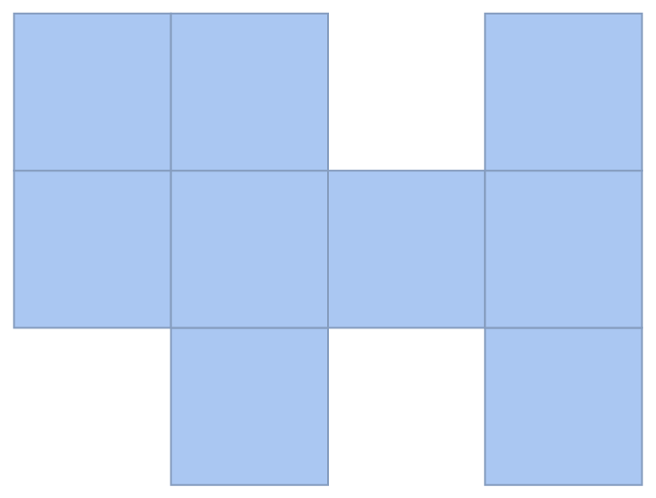
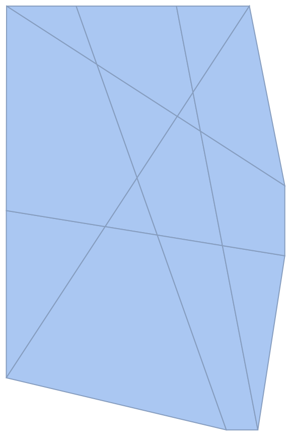
In simple words, I would like the squares/tiles in the image (see example below).
More precisely, I want a list of minimally sized regions whose union is equal to the union of lines of the input. I add minimally because in principle one might consider a subset of the union of squares/tiles.
The more precise request makes it a bit more difficult to understand but basically i would like to obtain the list of tiles that pave the image, the elements of the tessellation.
Example:
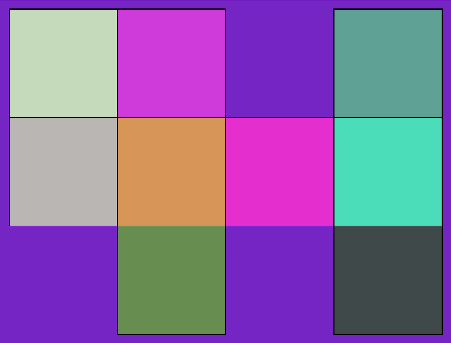
For the first input example above I would like the list:
ArrayMesh[{{1, 1, 0, 1}, {1, 1, 1, 1}, {0, 1, 0, 1}}] //
MeshPrimitives[#, 2] &


(* {Polygon[{{1., 2.}, {1., 3.}, {0., 3.}, {0., 2.}}], Polygon[{{2.,
  2.}, {2., 3.}, {1., 3.}, {1., 2.}}], Polygon[{{4., 2.}, {4., 3.}, {
  3., 3.}, {3., 2.}}], Polygon[{{1., 1.}, {1., 2.}, {0., 2.}, {0.,
  1.}}], Polygon[{{2., 1.}, {2., 2.}, {1., 2.}, {1., 1.}}], Polygon[{{
  3., 1.}, {3., 2.}, {2., 2.}, {2., 1.}}], Polygon[{{4., 1.}, {4.,
  2.}, {3., 2.}, {3., 1.}}], Polygon[{{2., 0.}, {2., 1.}, {1., 1.}, {
  1., 0.}}], Polygon[{{4., 0.}, {4., 1.}, {3., 1.}, {3., 0.}}]} *)
Visualization (each color roughly represents a polygon in the list above):
Optimal solution for me
A solution that only uses geometry and graphics. In particular I want to avoid solutions that convert the graphics object to an image because I am unable to get Mathematica to use the right image size while preserving resolution.
Possible solutions
Geometric solution
One could maybe add a point very close to each line to turn the line to a triangle and then use RegionDifference of the RegionUnion of the modified lines (that are now triangles) with the BoundaryRegion of the RegionUnion of the lines (basically getting the complement region).
This solution is a bit ugly I do not really like it and have not tried it yet
Image solution
One could use ComponentMeasurements or // ImageMesh // ConnectedMeshComponents but this has the issue that it converts the graphics object to an image which changes the scale and then the scale of the rectangles are not the same as the original rectangles
Graph solution
One could convert the lines to points and lines using // Apply[RegionUnion] // DiscretizeRegion and then to a graph to search for cycles. I do not know how to do this at the moment but I might consider searching for ways to do that

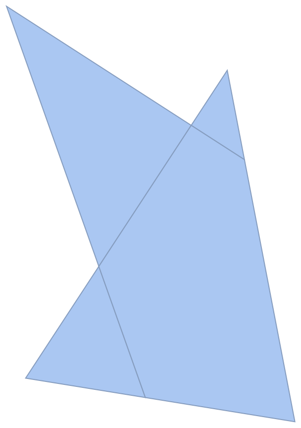
Polygon /@ FindCycle[Graph[First /@ Apply[UndirectedEdge, lines, {2}]], {4}, All][[All, All, 1]]wherelinesis your list of lines. $\endgroup$RegionUnionwhich adds the intersections. The full solution is then:lines // Apply[RegionUnion] // MeshPrimitives[#, 1] & // ReplaceAll[Line -> Identity] // MapApply[UndirectedEdge] // FindCycle[#, {4}, All] & // ReplaceAll[UndirectedEdge -> List] // Map[CrossingPolygon]$\endgroup$