13
$\begingroup$

Consider a self-intersecting non-convex polygon:

points = {{0, 0}, {2, 0}, {11, 4}, {-1, 4}, {4, .5}, {6, 7}, {7, 
0}, {10, 0}, {10, 6}, {0, 6}};

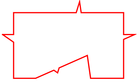
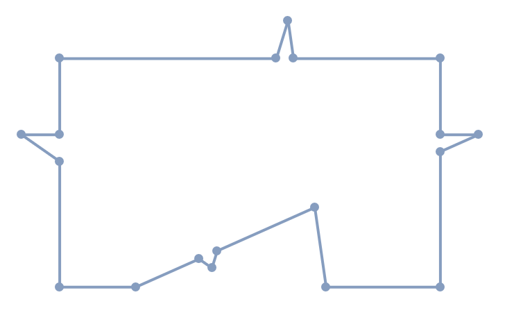
I need to find the polygon's outer boundary (in red):

boundary={{0,0},{2,0},{3.660194174757282,0.7378640776699029},{4,0.5},{4.138613861386139,0.9504950495049506},{6.701492537313434,2.0895522388059704},{7,0},{10,0},{10,3.555555555555556},{10,4},{10,6},{6.142857142857142,6},{6,7},{5.692307692307692,6},{5.692307692307692,6},{0,6},{0,4},{-1,4},{0,3.3000000000000003}};

{
Graphics@Thread@Line@Transpose[{points, RotateLeft@points}],
 Graphics@{Red, Thread@Line@Transpose[{boundary, RotateLeft@boundary}]}
}

enter image description here

WindingPolygon, OuterPolygon and their combinations fail:

{
Graphics@Thread@Line@Transpose[{#,RotateLeft@#}]&@WindingPolygon[points][[1]],
Graphics@Thread@Line@Transpose[{#,RotateLeft@#}]&@OuterPolygon[Polygon@points][[1]],
Graphics@Thread@Line@Transpose[{#,RotateLeft@#}]&@OuterPolygon[WindingPolygon[points]][[1]]
}

enter image description here

What is the proper way to solve this problem?

$\endgroup$

4 Answers 4

7
$\begingroup$

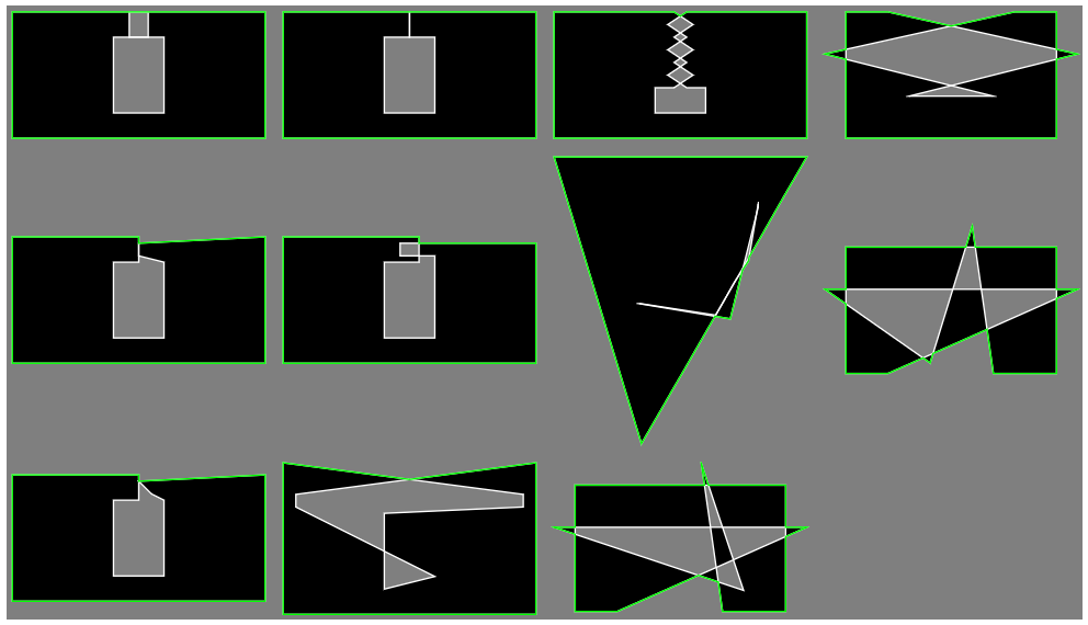
Apply my function contourPolygon on coordinates of a polygon. (output is already a polygon)

Use preset tms variable from @Anton answer.

contourPolygon[x_] := 
 Polygon[#[[1]][[First@FirstCase[#, _Rule, {#[[2]]}, All]]]] &@
  CrossingPolygon[x]

Graphics[{EdgeForm[White], Polygon[#], FaceForm[None], 
     EdgeForm[{Green}], contourPolygon[#]}] & /@ tms // 
 Multicolumn[#, Background -> Gray] &

enter image description here

$\endgroup$
7
  • $\begingroup$ Now we're talking $\endgroup$
    – Anton
    Commented Nov 12 at 4:48
  • $\begingroup$ How come this CrossingPolygon functionality is not mentioned anywhere in documentation? CrossingPolygon[points][[2]] gives all that is necessary, but is somehow omitted Help. $\endgroup$
    – Anton
    Commented Nov 12 at 8:08
  • $\begingroup$ @cvgmt Yes, but may not work for some special cases, like for example points {{0, 0}, {0, 1}, {1, 0}, {1, 1}}. $\endgroup$ Commented Nov 12 at 10:24
  • $\begingroup$ @cvgmt In fact your code does not work. Look at Graphics[{EdgeForm[Red], CrossingPolygon[tm9] /. Rule[a_, b_] :> a}] or instead of tm9 use tm1 or tm2. $\endgroup$ Commented Nov 12 at 10:38
  • $\begingroup$ @Anton I agree, the second argument of output of CrossingPolygon is not well explained in the documentation. Also notice that code in cvgmt's comment above does not work as can be seen by code in my previous comment. $\endgroup$ Commented Nov 12 at 10:42
11
$\begingroup$
points = {{0, 0}, {2, 0}, {11, 4}, {-1, 4}, {4, .5}, {6, 7}, {7, 
    0}, {10, 0}, {10, 6}, {0, 6}};

poly = Polygon@points;

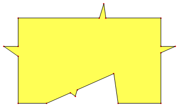
pts = RegionUnion[poly, DiscretizeRegion@OuterPolygon@poly] // 
   MeshPrimitives[#, 0] & // Map[Apply[Sequence]]

Graphics[{Lighter@Yellow, Polygon@pts, Red, Point@pts, Black, 
  Line@(Join[pts, {First@pts}])}]

polygon showing outer boundary method-1


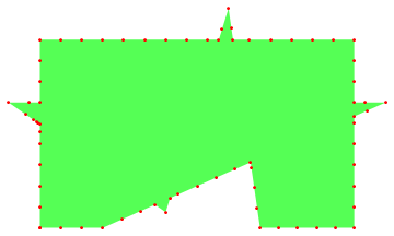
Using RegionBoundary:

pts = DiscretizeRegion[poly] // RegionBoundary // 
    MeshPrimitives[#, 0] & // Map[Apply[Sequence]];
fst = FindShortestTour[pts];
pts[[Last@fst]] // 
 Graphics[{Lighter@Green, Polygon@#, Red, Point@#}] &

polygon showing outer boundary method-2

$\endgroup$
5
  • $\begingroup$ RegionUnion[poly, OuterPolygon@poly] does not work on my system (WM 14.0 Windows). $\endgroup$
    – Anton
    Commented Nov 9 at 19:31
  • $\begingroup$ In computing pts in the first set of codes, the following error occurs: Part::partw: Part 2 of Line[{{{-1.,4.},{0.,3.3}},{{0.,0.},{2.,0.}},{{0.,3.3},{0.,0.}},{{3.66019,0.737864},{4.,0.5}},{{<<18>>,<<3>>},<<1>>},<<1>>,{{6.14286,6.},{6.42857,4.}},{{6.42857,4.},{6.70149,2.08955}},{{7.,0.},{10.,0.}},{{10.,3.55556},{11.,4.}}}] does not exist. "14.1.0 for Mac OS X ARM (64-bit) (July 16, 2024)" $\endgroup$
    – A. Kato
    Commented Nov 10 at 4:52
  • $\begingroup$ Sorry about the omission. I have updated the first answer to include DiscretizeRegion. $\endgroup$
    – Syed
    Commented Nov 10 at 5:04
  • $\begingroup$ RegionUnion[poly, DiscretizeRegion@OuterPolygon@poly] crashes on 14.0 $\endgroup$
    – Anton
    Commented Nov 10 at 6:21
  • $\begingroup$ I use v12.2 so can't say that I know how to fix/alter it for more recent versions. $\endgroup$
    – Syed
    Commented Nov 10 at 6:42
6
$\begingroup$
  • We add a large Rectangle which contain the Polygon and use RegionDifference to clip the Polygon.

  • After that we use InnerPolygon to get the "boundary" desired region.

  • I test this method in version 12.2,12.3, 13.3.1,14.0 but does not work in 14.1, it is a bug of 14.1 since the result of RegionDifference is wrong.

rectangle = 
  Rectangle @@ 
   Transpose@CoordinateBounds[Transpose@RegionBounds[poly], 1.5];
regout = BoundaryMesh[rectangle];
reg = RegionDifference[regout, poly];
regin = InnerPolygon[reg];
{regout, Region@poly, reg}
Graphics[{Red, RegionBoundary[regin]}]
  • The correct result of RegionDifference should be (version 13.3.1 and 14.0 is right, version 12.2,12.3 and 14.1 is wrong)
  • For version 12.2 and 12.3, when we set poly = WindingPolygon[points, "NonzeroRule"]; then all the result is correct.

enter image description here

enter image description here

  • If we don't not want to use InnerPolygon, we can also extract the MeshCells in the region.
MeshRegion[MeshCoordinates[reg], 
 MeshCells[reg, 1, "Multicells" -> True][[2]]]

or

BoundaryMeshRegion[MeshCoordinates[reg], 
  MeshCells[reg, 1, "Multicells" -> True][[2]]] // RegionBoundary

enter image description here

$\endgroup$
5
  • $\begingroup$ regin is EmptyRegion[2] on 14.1.0 for Mac OS X ARM (64-bit) (July 16, 2024). $\endgroup$
    – A. Kato
    Commented Nov 10 at 4:48
  • $\begingroup$ @A.Kato Since RegionDifference is wrong in version 14.1 $\endgroup$
    – cvgmt
    Commented Nov 10 at 5:01
  • $\begingroup$ For version 14.1, we have to use ImageMesh. Clear[points, poly, rectangle, g]; points = {{0, 0}, {2, 0}, {11, 4}, {-1, 4}, {4, .5}, {6, 7}, {7, 0}, {10, 0}, {10, 6}, {0, 6}}; poly = WindingPolygon[points, "NonzeroRule"]; rectangle = Rectangle @@ Transpose@CoordinateBounds[points, .5]; g = Graphics[{rectangle, White, poly}] // ImageMesh; BoundaryMeshRegion[MeshCoordinates[g], MeshCells[g, 1, "Multicells" -> True][[2]]] // RegionBoundary $\endgroup$
    – cvgmt
    Commented Nov 10 at 8:40
  • $\begingroup$ @cvgmt ImageMesh does not give a precise solution. $\endgroup$
    – Anton
    Commented Nov 11 at 8:32
  • $\begingroup$ @Anton That is why I just add a comments. $\endgroup$
    – cvgmt
    Commented Nov 11 at 9:47
3
$\begingroup$

Here's a more generalized solution, based on @cvgmt's approach.

Toy models:

tm1={{-10,-5},{10,-5},{10,5},{-0.75,5},{-0.75,3},{2,3},{2,-3},{-2,-3},{-2,3},{0.75,3},{0.75,5},{-10,5}};
tm2={{-10,-5},{10,-5},{10,5},{0,4.5},{0,3.5},{2,3},{2,-3},{-2,-3},{-2,3},{0,3},{0,5},{-10,5}};
tm3={{-10,-5},{10,-5},{10,5},{0,4.5},{1,3.5},{2,3},{2,-3},{-2,-3},{-2,3},{0,3},{0,5},{-10,5}};
tm4={{-10,-5},{10,-5},{10,5},{0,5},{0,3},{2,3},{2,-3},{-2,-3},{-2,3},{0,3},{0,5},{-10,5}};
tm5={{-10,-5},{10,-5},{10,4.5},{-0.75,4.5},{-0.75,3.5},{2,3.5},{2,-3},{-2,-3},{-2,3},{0.75,3},{0.75,5},{-10,5}};
tm6={{-10,-5},{10,-5},{10,7},{-9,4.5},{-9,3.5},{2,-2},{-2,-3},{-2,3},{9,3.5},{9,4.5},{-10,7}};
tm7={{-10,-5},{10,-5},{10,5},{.5,5},{-1,4},{.5,3},{-1,2},{.5,1},{-1,0},{.5,-1},{2,-1},{2,-3},{-2,-3},{-2,-1},{-.5,-1},{1,0},{-.5,1},{1,2},{-.5,3},{1,4},{-.5,5},{-10,5}};
tm8={{13876.088285207748`,13583.902501240373`},{13901.698801517487`,13628.228394724429`},{13919.968444108963`,13659.692779097706`},{13935.85636305809`,13687.496636971831`},{13963.85636305809`,13735.496636971831`},{13980.172897577286`,13764.05057232827`},{13998.918132781982`,13796.608086518943`},{14040.546700874964`,13868.696582235396`},{14060.004526236118`,13903.382270960472`},{14087.774329972268`,13945.03697647041`},{14106.99999988079`,14057.987787880003`},{14107.`,14051.3012342304`},{14051.902840881348`,13830.91259828031`},{13871.37843067944`,13861.`},{13874.793525728837`,13861.`},{14022.955277819834`,13838.205884293207`},{14115.38800375802`,13998.422609171696`},{14128.616750717163`,14021.82731544599`},{14159.856363117695`,14076.496637016535`},{14187.85636305809`,14124.496636971831`},{14203.167274781636`,14151.290732435882`},{13703.167274781636`,14151.290732435882`}};
tm9={{0,0},{2,0},{11,4},{-1,4},{8,1},{6,7},{7,0},{10,0},{10,6},{0,6}};
tm10={{0,0},{10,0},{10,6},{8,6},{-1,4},{7,2},{3,2},{11,4},{2,6},{0,6}};
tm11={{0,0},{2,0},{11,4},{-1,4},{4,0.5},{6,7},{7,0},{10,0},{10,6},{0,6}};

tms = {tm1, tm2, tm3, tm4, tm5, tm6, tm7, tm8, tm9, tm10, tm11};

First, we go along with @cvgmt go get the reg:

outerContour[points_]:=Module[{cb,reg,segs,fcs,mc,reg1,mc1,polys,segs1,tal},
cb=CoordinateBounds[points,.5];
reg=RegionDifference[BoundaryMesh[Rectangle@@Transpose@cb],Polygon@points];

Get rid of first four (those are from the rectangle), to get the intersected line segments:

segs=Drop[Sort@MeshCells[reg,1][[All,1]],4];

We turn these segments into an undirected graph; its FindFundamentalCycles give us a set of polygons which we can merge to get a non-intersecting polygon representation, which is then triangulated:

fcs=FindFundamentalCycles@Graph[UndirectedEdge@@@segs];
mc=MeshCoordinates@reg;
reg1=DiscretizeGraphics@Graphics`PolygonUtils`PolygonUnion[Polygon@#&/@(mc[[#]]&/@fcs[[All,All,1]])];
mc1=MeshCoordinates@reg1;
polys=MeshCells[reg1,2][[All,1]];

FInally, those triangles' segments are counted with Tally, so those that are only counted once, make up the boundary we are after:

segs1=Sort/@Flatten[Transpose[{#,RotateLeft@#}]&/@polys,1];
Partition[mc1[[Flatten[Pick[tal=Tally@segs1;tal[[All,1]],tal[[All,2]],1],1]]],2]
];

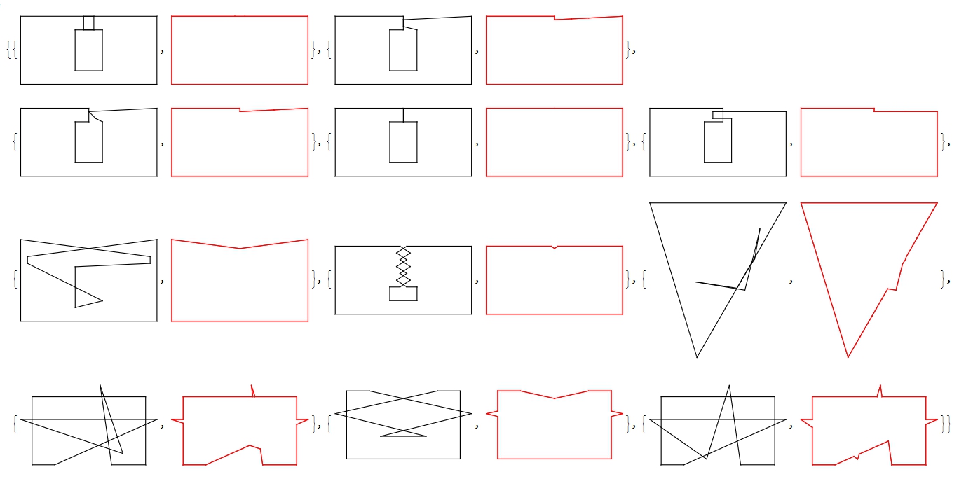
{Graphics@{Thread@Line@Transpose[{#,RotateLeft@#}]},Graphics@{Red,Thread@Line@Transpose[{outerC=outerContour[#];outerC,RotateLeft@outerC}]}}&/@tms

FindFundamentalCycles seems to do the job, though it's not obvious why it always generates cycles that cover 100% of any Polygon@points. But it does, in all my toy model cases.
enter image description here

UPD.

Based on @azerbajdzan solution, a bit cleaner:
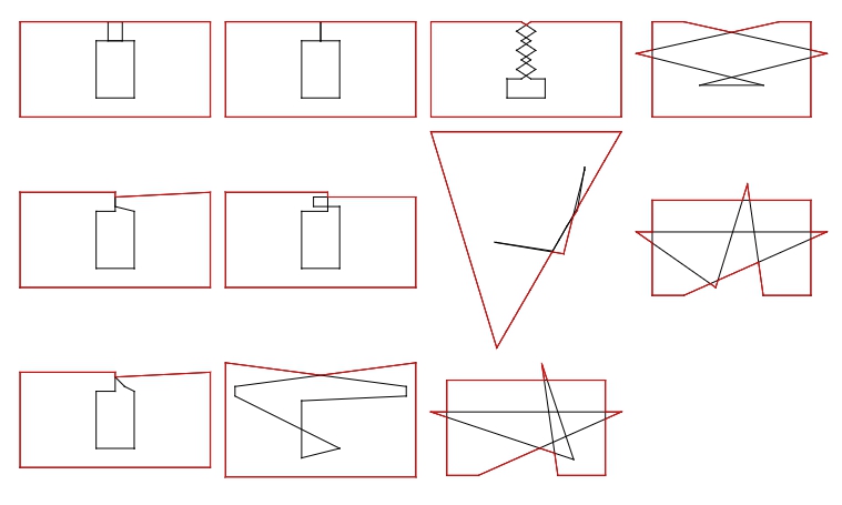
contourPolygon1[x_] := 
 Polygon[#[[1]][[FirstCase[#[[2]], _List, #[[2]], All]]]] &@
  CrossingPolygon[x]

Graphics[{EdgeForm[Black], Thread@Line@Transpose[{#, RotateLeft@#}], 
     FaceForm[None], EdgeForm[{Red}], contourPolygon1[#]}] & /@ tms //
  Multicolumn[#] &
enter image description here

$\endgroup$

Your Answer

By clicking “Post Your Answer”, you agree to our terms of service and acknowledge you have read our privacy policy.

Not the answer you're looking for? Browse other questions tagged or ask your own question.