I'm trying to write code to create a circuit from its connection information.
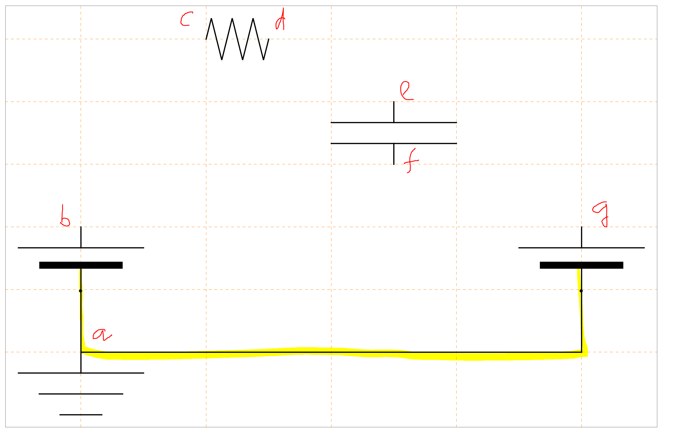
For example, in the image below you see an incompleted circuit with two batteries, one resistor and one capacitor. The position of two battery and ground connection is assumed to be fixed (on the left right side and bottom as in the image). However, the resistor and capacitor and switch can be placed in any position.
Also the nodes are marked with letters a, b, c, d, e, f, g as in the image.
Now assume that I have information such as:
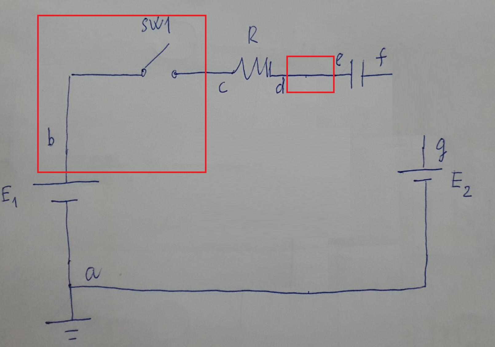
{"b","sw" "c"}: add a switch between nodeband nodec.{"d","wire" "e"}: add a wire between nodedand nodee.
So you would form a connection like this.
So if I have a connection input like this:
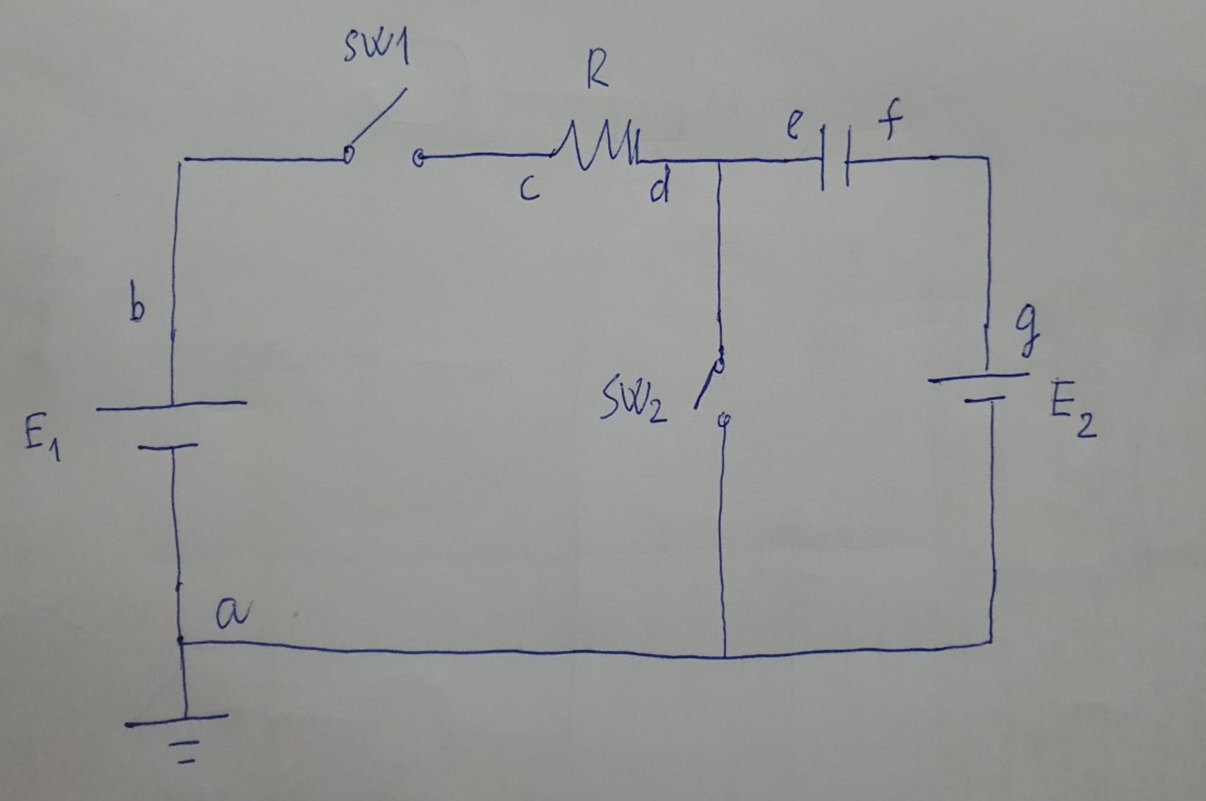
connection = {{"b", "sw", "c"}, {"d", "wire", "e"}, {"d", "sw", "a"}, {"f","wire", "g"}}
The expected output circuit would be something like this. The output circuit is not unique. It can be any shape but I'm looking for a method to make a good shape like this with no overlaping and looks nice.
Here is my current code:
The first part is some basic components from the previous post and with my ground[] function a
    resistor[l_ : 1, n_ : 3] :=
 Line[Table[{i l/(4 n), 1/3 Sin[i Pi/2]}, {i, 0, 4 n}]]

coil[l_ : 1, n_ : 3] :=
 Module[{scale = l/(5/16 n + 1/2),
   pts = {{0, 0}, {0, 1}, {1/2, 1}, {1/2,
      0}, {1/2, -1}, {5/16, -1}, {5/16, 0}}},
  Append[Table[
    BezierCurve[scale Map[{d 5/16, 0} + # &, pts]], {d, 0, n - 1}],
   BezierCurve[scale Map[{5/16 n, 0} + # &, pts[[1 ;; 4]]]]]]

capacitor[l_ : 1] := {gap[l],
  Line[l {{{1/3, -1}, {1/3, 1}}, {{2/3, -1}, {2/3, 1}}}]}

battery[l_ : 1] := {gap[
   l], {Rectangle[l {1/3, -(2/3)}, l {1/3 + 1/9, 2/3}],
   Line[l {{2/3, -1}, {2/3, 1}}]}}

contact[l_ : 1] := {gap[l],
  Map[{EdgeForm[Directive[Thick, Black]], FaceForm[White],
     Disk[#, l/30]} &, l {{1/3, 0}, {2/3, 0}}]}

ground[l_ : 1] := {Line[l {{2/3, 0}, {1, 0}}],
  Line[l {{2/3, -1}, {2/3, 1}}], Line[l {{1/3, -2/3}, {1/3, 2/3}}],
  Line[l {{0, -1/3}, {0, 1/3}}]}

Options[display] = {Frame -> True, FrameTicks -> None,
   PlotRange -> All, GridLines -> Automatic,
   GridLinesStyle -> Directive[Orange, Dashed],
   AspectRatio -> Automatic};
display[d_, opts : OptionsPattern[]] :=
 Graphics[Style[d, Thick],
  Join[FilterRules[{opts}, Options[Graphics]], Options[display]]]

at[position_, angle_ : 0][obj_] :=
 GeometricTransformation[obj,
  Composition[TranslationTransform[position],
   RotationTransform[angle]]]

label[s_String, color_ : RGBColor[.3, .5, .8]] :=
  Text@Style[s, FontColor -> color, FontFamily -> "Geneva",
    FontSize -> Large];

connect[pointList_] := {Line[pointList],
  Map[Text[Style[
      "\!\(\*AdjustmentBox[\(\[Bullet]\),\n\
BoxBaselineShift->0.24615384615384617`,\nBoxMargins->{{0., 0.}, \
{-0.24615384615384617`, 0.24615384615384617`}}]\)",
      FontSize -> 18], #] &, pointList[[{1, -1}]]]}

gap[l_ : 1] := Line[l {{{0, 0}, {1/3, 0}}, {{2/3, 0}, {1, 0}}}]
And this is my code to create the circuit:
    connection = {{"b", "sw", "c"}, {"d", "wire", "e"}, {"d", "sw", "a"}, {"f","wire", "g"}}
display[
     {battery[] // at[{0, 0}, Pi/2],
      battery[] // at[{8, 0}, Pi/2],
      ground[] // at[{0, -2}, Pi/2],
      connect[{{0, 0}, {0, -1}, {8, -1}, {8, 0}}],
      capacitor[] // at[{5, 2}, Pi/2],
      resistor[] // at[{2, 4}]}]
How can I create circuit from this with nice looking?
Note that the connection input can be changed and would be nice to have a circuit still looks good with that changes.
Currently I'm stuck at insert a switch or a wire between two nodes and organize to form a nice shape.


