2
$\begingroup$

I have defined a 3 support beam, with a uniform load over part of the span. The end BC are simple to define - deflection and moment = 0. The midspan BC for deflection =0 but but the moment can not be defined at Ls/2 location. I know that there must be slope continuity across the joint - how to define that in the code ? When I define the midspan pin support w @Ls/2 = 0 I still get an error "No places were found on the boundary where x==30. was True, so DirichletCondition[w==0,x==30.] will effectively be ignored."

The plots produced show BC @ 0 and Ls are correct.

(*Define parameters*)
Ls = 60 ;(*Length of the beam in inches*)
Es = 10000000; (*Young's modulus in psi*)
Is = 10; (*Moment of inertia in in^4*)
qs = -50;(*Uniform load in pli applied over full length of beam *)
qss = -100; (* seam load over 4 inches*)
lss = 45; (*seam start location from left edge *)
(*Load function definition*)
loadFunction1[x_] := (If[x >= lss, If[x >= (lss + 15), qss, qss], qs]);
Plot[loadFunction1[x], {x, 0, Ls}, 
 PlotLabel -> "Loading on beam, pli", 
 AxesLabel -> {"x dist along beam", " pli units"}]

(*loadFunction[x_]:=If[x<=Ls/2,qs,0];
Plot[loadFunction[x],{x,0,Ls},PlotLabel->"Loading on beam, \
pli",AxesLabel->{"x dist along beam"," pli units"}]*)
(*Beam equation setup using FEM*)
Needs["NDSolve`FEM`"];
additionalPoints = {{Ls/2}}
beamDomain = 
 ToElementMesh[ImplicitRegion[0 <= x <= Ls, x], 
   "IncludePoints" -> additionalPoints]["Wireframe"]

(*Boundary conditions for a simply supported beam*)
boundaryConditions = {w[0] == 0, w[Ls/2] == 0, w[Ls] == 0, 
   moment[0] == 0,(*moment[Ls/2]==0,*)moment[Ls] == 0};

(*Beam equation*)
beamPDE = {D[moment[x], {x, 2}] + loadFunction1[x] == 0, 
   moment[x] == -Es*Is*D[w[x], {x, 2}]};

(*Solve the beam equation using NDSolve with FEM*)
(*solution=NDSolveValue[{beamPDE,boundaryConditions,\
DirichletCondition[{w[Ls/2]\[Equal]0,moment[Ls/2]\[Equal]0},True]},{w,\
moment},{x,0,Ls},Method->{"FiniteElement"}];*)
solution = 
  NDSolveValue[{beamPDE, boundaryConditions}, {w, moment}, {x, 0, Ls},
    Method -> {"FiniteElement"}];

(*Plot the deflection diagram*)
Plot[solution[[1]][x], {x, 0, Ls}, PlotLabel -> "Deflection Diagram", 
 AxesLabel -> {"x (m)", "w(x) (m)"}]

(*Calculate shear force V(x)=-EI*d^3w/dx^3*)
shearForce = -Es*Is*D[solution[x], {x, 3}];
(*Plot the shear force diagram*)
Plot[solution[[2]]'[x], {x, 0, Ls}, 
 PlotLabel -> "Shear Force Diagram", 
 AxesLabel -> {"x (m)", "V(x) (N)"}]


(*Plot the bending moment diagram*)
Plot[solution[[2]][x], {x, 0, Ls}, 
 PlotLabel -> "Bending Moment Diagram", 
 AxesLabel -> {"x (m)", "M(x) (N*m)"}]
$\endgroup$
3
  • 1
    $\begingroup$ What does the title mean? Can you say it in other words? TIA. $\endgroup$
    – user64494
    Commented Jun 2 at 17:02
  • $\begingroup$ @SAK Perhaps clearer title " Finite Element beam model with three supports" $\endgroup$ Commented Jun 2 at 17:42
  • 1
    $\begingroup$ @SAK There is an error in the meshdefinition : Change to beamDomain = ToElementMesh[ImplicitRegion[0 <= x <= Ls, x], "IncludePoints" -> additionalPoints] (without ["Wireframe"]) $\endgroup$ Commented Jun 3 at 8:18

2 Answers 2

2
$\begingroup$

With modified mesh

Needs["NDSolve`FEM`"];
additionalPoints = {{Ls/2 }}
beamDomain =ToElementMesh[ImplicitRegion[0 <= x <= Ls, x], "IncludePoints" -> additionalPoints, "MeshOrder" -> 1]

and load

q[x_] := Piecewise[{{qs, 0 <= x <= lss}, {qss, lss < x <= Ls}}]

we can confirm result derived by @BillWatts using FiniteElement, if we include correct boundary condition moment[Ls/2]==-(219375/32).

solution = 
 NDSolveValue[{{D[moment[x], {x, 2}] + q[x] == 0, 
    moment[x] == -Es Is*D[w[x], {x, 2}]}, {w[0] == 0, 
    DirichletCondition[w[x] == 0, x == Ls/2], w[Ls] == 0, 
    moment[0] == 0, 
    DirichletCondition[moment[x] == -(219375/32), x == Ls/2], 
    moment[Ls] == 0}}, {w, moment}, Element[x, beamDomain]  , 
  Method -> {"FiniteElement"} ] 

GraphicsRow[{Plot[solution[[1]][x], {x, 0, Ls}], Plot[solution[[2]][x], {x, 0, Ls}]}]

enter image description here

The question remains how to get these inner boundary condition directly without friendly support by classical beam theory (thanks @Bill Watts) ?

I tried, still without success, to find the NeumannValue of this problem.

Any ideas from FEM experts?

$\endgroup$
6
  • 1
    $\begingroup$ I think the problem is that the moment at the middle of the beam is not a boundary condition. It cannot be specified arbitrarily without getting nonesense. If you specify the moment as a bc, then you will not necessarily satisfy the displacements at the supports, which are the true bc's. Mathematica will solve the displacement ode analytically without bc's, but then you will have to apply the bc's yourself to solve for p1 and the arbitrary constants. $\endgroup$
    – Bill Watts
    Commented Jun 3 at 19:10
  • $\begingroup$ @BillWatts Thanks for your comment. FEM allows an inner point to be a boundary. Displacement condition is easily accepted, the way how to find the second condition is not obvious. On the other hand, if we solve this beamproblem with energymethods the inner boundarycondition is easy to implement $\endgroup$ Commented Jun 3 at 21:03
  • 1
    $\begingroup$ We have an inner boundary, but it is displacement, not moment. It's not that we mathematically cannot specify moment at the inner boundary, it's that in this case, it doesn't really make much sense. $\endgroup$
    – Bill Watts
    Commented Jun 3 at 21:09
  • $\begingroup$ Boundary conditions are normally given at the start of the problem. In this case, the moment at the middle of the beam is an unknown to be solved for. $\endgroup$
    – Bill Watts
    Commented Jun 3 at 21:13
  • $\begingroup$ I think Dirichlet and Neumann boundary conditions make both "sense" $\endgroup$ Commented Jun 3 at 21:26
0
$\begingroup$

Looking at the plot I get for the moment at x=30, I don't see how you can solve it the way you are doing it. Try this.

(*Define parameters*)`
Ls = 60 ;(*Length of the beam in inches*)
Es = 10000000; (*Young's modulus in psi*)
Is = 10; (*Moment of inertia in in^4*)
qs = -50;(*Uniform load in pli applied over full length of beam *)
qss = -100; (* seam load over 4 inches*)
lss = 45; (*seam start location from left edge *)

We have three supports

p1 at x = 0

p2 at x = 30

p3 at x = Ls

Being statically indeterminant we can only find two of the three in terms of the other using only forces and torques. Find p2 and p3 in terms of p1.

The torque about x = 0.

eq1 = Integrate[qs*x, {x, 0, lss}] + Integrate[qss*x, {x, lss, Ls}] + p2*(Ls/2) + p3*Ls == 0

The second equation comes from the sum of the forces = 0

eq2 = p1 + p2 + p3 + qs*lss + qss*(Ls - lss) == 0

solp = Solve[{eq1, eq2}, {p2, p3}] // Flatten
(*{p2->1/2 (6375-4 p1),p3->1/2 (2 p1+1125)}*)

Now the load function for all the loads is

p[x_] = p1  DiracDelta[x] + p2  DiracDelta[x - Ls/2] + p3  DiracDelta[x - Ls] + qs + qss/2  UnitStep[x - 3  Ls/4] - qss  UnitStep[x - Ls]

EI = Es  Is

Now instead of using the differential equation for the moment, use the differential equation for the displacement.

ode = v''''[x] == p[x]/EI /. solp

or write as

v4[x_] = p[x]/EI /. solp

Integrate to get v'''[x]

v3[x_] = Integrate[v4[x], x] + c1 // Simplify

Integrate to get v''[x]

v2[x_] = Integrate[v3[x], x] + c2 // Simplify

And v'[x]

v1[x_] = Integrate[v2[x], x] + c3 // Simplify

and the displacement v[x]

v[x_] = Integrate[v1[x], x] + c4

Now we know v2[x] is proportional to the moment which is zero at the endpoints. So solve for some of the c's.

at x = 0

v2[0] == 0
(*c2==0*)

c2 = 0

v2[Ls] == 0 // Expand
(*60 c1==0*)

c1 = 0

The displacements at the supports are zero.

v[0] == 0
(*c4==0*)

We can solve for p1 and c3 by use of the other supports

solpc = Solve[{v[Ls] == 0, v[Ls/2] == 0}, {p1, c3}] // Flatten
(*{p1->33375/64,c3->-(9/40960)}*)

p1 = p1 /. solpc
c3 = c3 /. solpc

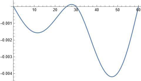
The displacement

Plot[v[x], {x, 0, Ls}]

enter image description here

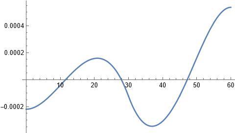
the slope

slope[x_] = v1[x] // Simplify

Plot[slope[x], {x, 0, Ls}]

enter image description here

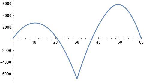
The moment

m[x_] = EI  v2[x]

Plot[m[x], {x, 0, Ls}]

enter image description here

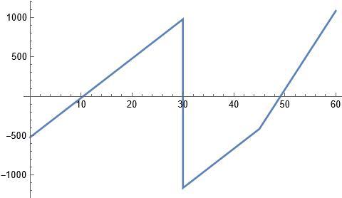
The shear

shear[x_] = -EI  v3[x]

Plot[shear[x], {x, 0, Ls}, Exclusions -> None]

enter image description here

As Requested

Ls = 60;
Es = 10000000; 
Is = 10; 
qs = -50; 
qss = -100; 
lss = 45; 
eq1 = Integrate[qs*x, {x, 0, lss}] + Integrate[qss*x, {x, lss, Ls}] + p2*(Ls/2) + p3*Ls == 0;
eq2 = p1 + p2 + p3 + qs*lss + qss*(Ls - lss) == 0;
solp = Flatten[Solve[{eq1, eq2}, {p2, p3}]];
p[x_] = p1*DiracDelta[x] + p2*DiracDelta[x - Ls/2] + p3*DiracDelta[x - Ls] + qs + (qss/2)*UnitStep[x - 3*(Ls/4)] -qss*UnitStep[x - Ls];
EI=Es*Is;
ode = v''''[x] == p[x]/EI /. solp;
v4[x_] = p[x]/EI /. solp;
v3[x_] = Integrate[v4[x], x] + c1 // Simplify;
v2[x_] = Integrate[v3[x], x] + c2 // Simplify;
v1[x_] = Integrate[v2[x], x] + c3 // Simplify;
v[x_] = Integrate[v1[x], x] + c4;

v2[0] == 0
c2 = 0
v2[Ls] == 0 // Expand
c1 = 0
v[0] == 0
c4 = 0
solpc = Solve[{v[Ls] == 0, v[Ls/2] == 0}, {p1, c3}] // Flatten
p1 = p1 /. solpc;
c3 = c3 /. solpc;
Plot[v[x], {x, 0, Ls}]
slope[x_] = v1[x] // Simplify;
Plot[slope[x], {x, 0, Ls}]
m[x_] = EI*v2[x]
Plot[m[x], {x, 0, Ls}]
shear[x_] = -EI*v3[x]
Plot[shear[x], {x, 0, Ls}, Exclusions -> None]
$\endgroup$
2
  • $\begingroup$ Bill Watts, can you post the complete code as executed without comments, inserts,etc.. I am having issues running this code by cutting and pasting - for example - I see that in some lines when I copy and paste into a blank workbook - there are 2 spaces between variables where I would place a "*" just to be sure the correct operation is used. $\endgroup$
    – SAK
    Commented Jul 15 at 18:21
  • $\begingroup$ Done. Hope it helps. $\endgroup$
    – Bill Watts
    Commented Jul 15 at 22:19

Your Answer

By clicking “Post Your Answer”, you agree to our terms of service and acknowledge you have read our privacy policy.

Not the answer you're looking for? Browse other questions tagged or ask your own question.