Based on Oleksandr's excellent design idea here is my re-implementation of his package which offers a much richer set of shapes.
UPDATE from July 2021
New version came out! Now it allows direct generation of Graphics objects that can be immediately used as markers for PlotMarkers. The new version contains no incompatible changes.
The Wolfram Function Repository version is also updated, but now it differs from the version published here and on GitHub in the sense that it does not include the general-purpose functions used to generate the built-in shapes on the fly at the package loading time. It was a decision made by the reviewer to define them simply as lists of points, probably for better performance. The functionality and syntax are the same.
UPDATE from October 2019
Now my function is published in the Wolfram Function Repository what means that it is available for users of Mathematica version 12.0 or higher as ResourceFunction["PolygonMarker"]. Users of previous versions should install the package as described below (the functionality is the same).
How to install the package
The most recent version of the package can be installed from GitHub by evaluating the following:
(* Load the package code *)
package =
  Import["http://raw.github.com/AlexeyPopkov/PolygonPlotMarkers/master/PolygonPlotMarkers.m", "Text"];

(* Install the package (existing file will be overwritten!) *)
Export[FileNameJoin[{$UserBaseDirectory, "Applications",
    "PolygonPlotMarkers.m"}], package, "Text"];
For manual installation copy the code from the bottom of this post and save it as "PolygonPlotMarkers.m" in the directory SystemOpen[FileNameJoin[{$UserBaseDirectory, "Applications"}]].
Description of the package
The basic usage syntax is
PolygonMarker[shape, size]whereshapeis a name of built-in shape or a list of 2D coordinates describing a non-selfintersecting polygon. Thesizecan be given as a number or inScaledorOffsetform.
PolygonMarker[All]andPolygonMarker[]return the list of names of built-in shapes.
PolygonMarker[shape, size]returnsPolygongraphics primitive which can be used inGraphics.
PolygonMarker[shape, size, style], wherestyleis a list of graphics directives applied toshape, returns aGraphicsobject which can be used as a marker forPlotMarkers.
PolygonMarker[shape, size, style, options]returns aGraphicsobject withoptionsapplied.With
Offsetsizespecification the plot marker has fixed size specified in printer's points independent of the size of the plot.
PolygonMarkers with identicalsizespecifications have equal areas (not counting the area taken by the edge of generatedPolygon).PolygonMarker[shape, size]returns shape with areasize2in the internal coordinate system ofGraphics.PolygonMarker[shape, Offset[size]]returns shape with areasize2square printer's points.The centroid of polygon returned by
PolygonMarker[shape, size]is always placed at{0, 0}in the internal coordinate system ofGraphics.
PolygonMarker[shape, size, positions]wherepositionsis a list of 2D coordinates evaluates toTranslate[PolygonMarker[shape, size], positions]. It represents a collection of multiple identical copies of the shape with centroids placed atpositions.
Basic examples of use
The complete list of built-in named shapes:
Needs["PolygonPlotMarkers`"]

allShapes = PolygonMarker[All]
Tooltip[PolygonMarker[#, 1,
    {FaceForm[Hue@Random[]], EdgeForm[{Black, AbsoluteThickness[0.5], JoinForm["Miter"]}]},
    {ImageSize -> 30, PlotRange -> 1.5, PlotRangePadding -> 0, ImagePadding -> 0}], #] & /@ allShapes
{"TripleCross", "Y", "UpTriangle", "UpTriangleTruncated", "DownTriangle",
"DownTriangleTruncated", "LeftTriangle", "LeftTriangleTruncated", "RightTriangle",
"RightTriangleTruncated", "ThreePointedStar", "Cross", "DiagonalCross", "Diamond",
"Square", "FourPointedStar", "DiagonalFourPointedStar", "FivefoldCross", "Pentagon",
"FivePointedStar", "FivePointedStarThick", "SixfoldCross", "Hexagon", "SixPointedStar",
"SixPointedStarSlim", "SevenfoldCross", "SevenPointedStar", "SevenPointedStarNeat",
"SevenPointedStarSlim", "EightfoldCross", "Disk", "H", "I", "N", "Z", "S", "Sw", "Sl"}
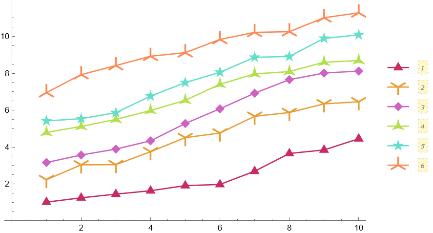
Automatic plot legends (Mathematica 10 or higher) often require a larger value for the LegendMarkerSize option in order to avoid cropping. Filled markers which pick up PlotStyle and PlotTheme automatically:
fm[name_String, size_ : 8] := PolygonMarker[name, Offset[size], EdgeForm[]];

SeedRandom[25];
ListPlot[Table[Accumulate@RandomReal[1, 10] + i, {i, 6}],
 PlotMarkers ->
  fm /@ {"Triangle", "Y", "Diamond", "ThreePointedStar", "FivePointedStar", "TripleCross"},
 PlotStyle -> ColorData[54, "ColorList"], Joined -> True,
 PlotLegends ->
  PointLegend[Automatic, LegendMarkerSize -> {50, 37},
   LegendLayout -> (Column[Row /@ #, Spacings -> -1] &)],
 ImageSize -> 450]
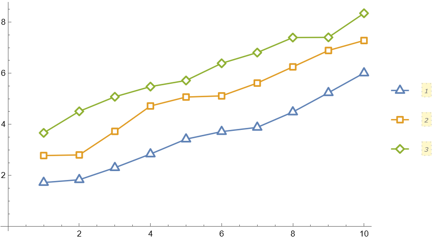
Empty markers which pick up PlotStyle and PlotTheme automatically:
em[name_String, size_ : 7] := PolygonMarker[name, Offset[size],
   {Dynamic@EdgeForm@Directive[CurrentValue["Color"], JoinForm["Round"], AbsoluteThickness[2], Opacity[1]], FaceForm[White]}, ImagePadding -> 6];

SeedRandom[2];
ListPlot[Table[Accumulate@RandomReal[1, 10] + i, {i, 3}],
 PlotMarkers -> em /@ {"Triangle", "Square", "Diamond"},
 Joined -> True,
 PlotLegends -> PointLegend[Automatic, LegendMarkerSize -> {40, 25}], ImageSize -> 450]

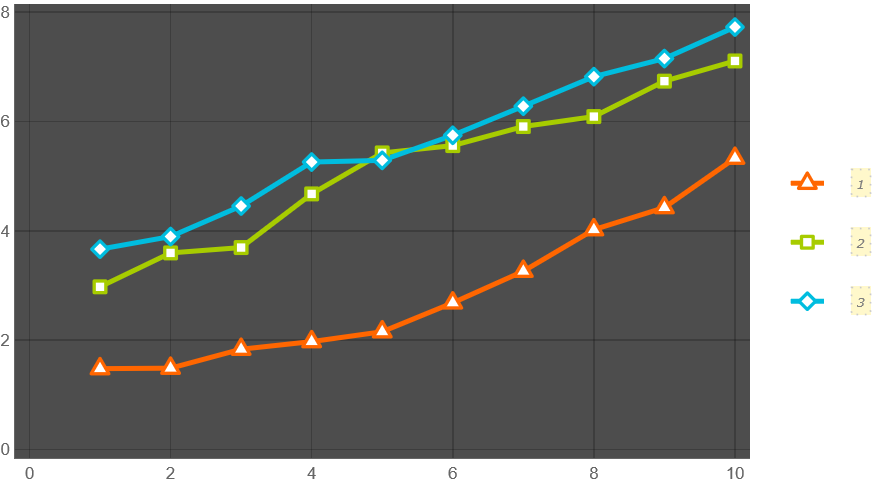
SeedRandom[3];
ListPlot[Table[Accumulate@RandomReal[1, 10] + i, {i, 3}],
 PlotMarkers -> em /@ {"Triangle", "Square", "Diamond"},
 Joined -> True,
 PlotLegends -> PointLegend[Automatic, LegendMarkerSize -> {40, 25}],
 PlotTheme -> "Marketing", ImageSize -> 450]
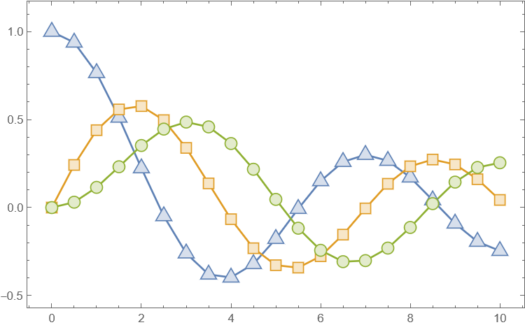
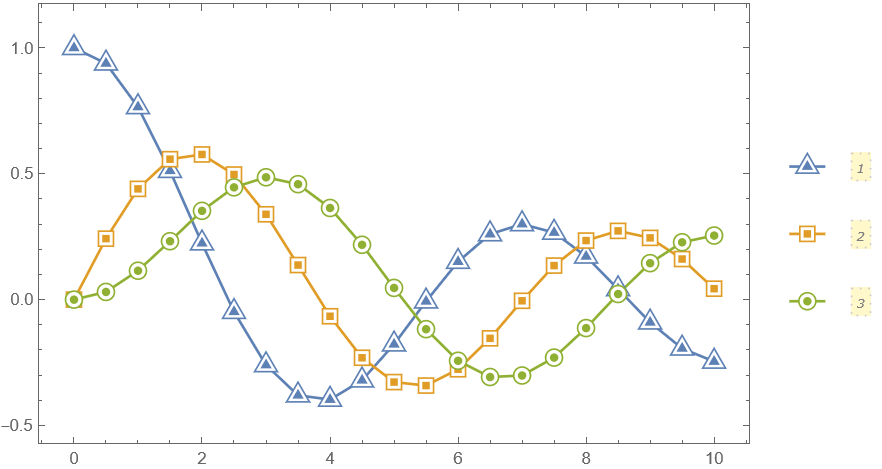
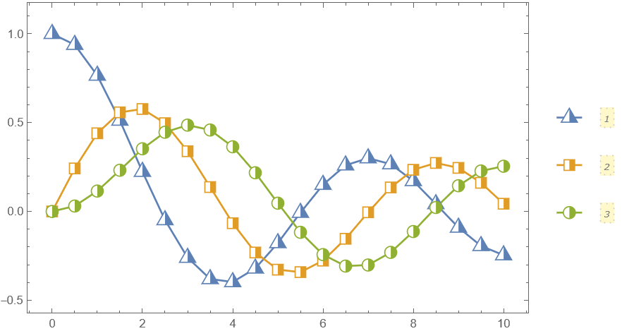
Filled markers with lighter filling colors:
fm2[name_String, size_ : 9] := PolygonMarker[name, Offset@size, {
    Dynamic@EdgeForm[{CurrentValue["Color"], Opacity[1]}],
    Dynamic@FaceForm@Lighter[CurrentValue["Color"], 0.75]}];

data = Table[{x, BesselJ[k, x]}, {k, 0, 2}, {x, 0, 10, 0.5}];

ListPlot[data,
 PlotMarkers -> fm2 /@ {"UpTriangle", "Square", "Circle"},
 Joined -> True, Frame -> True, Axes -> False, ImageSize -> 450,
 PlotRangePadding -> {Scaled[.05], Scaled[.1]}]
Advanced usage
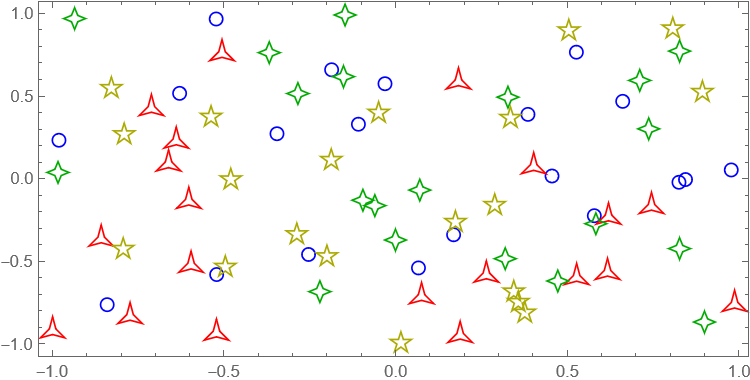
The third argument of PolygonMarker can be used to specify the coordinate(s) where the shape should be placed:
Graphics[{FaceForm[],EdgeForm[{AbsoluteThickness[1],JoinForm["Miter"]}],
       EdgeForm[Blue],PolygonMarker["Circle",Offset[7],RandomReal[{-1,1},{20,2}]],
       EdgeForm[Red],PolygonMarker["ThreePointedStar",Offset[7],RandomReal[{-1,1},{20,2}]],
       EdgeForm[Darker@Green],PolygonMarker["FourPointedStar",Offset[7],RandomReal[{-1,1},{20,2}]],
       EdgeForm[Darker@Yellow],PolygonMarker["FivePointedStar",Offset[7],RandomReal[{-1,1},{20,2}]]},
      AspectRatio->1/2,ImageSize->450,Frame->True]
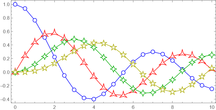
Construct a list plot directly from graphics primitives:
data = Table[{x, BesselJ[k, x]}, {k, 0, 3}, {x, 0, 10, 0.5}];
markers = {"Circle", "ThreePointedStar", "FourPointedStar", "FivePointedStar"};
colors = {Blue, Red, Darker@Green, Darker@Yellow};
Graphics[Table[{colors[[i]], Line[data[[i]]], FaceForm[White],
   EdgeForm[{colors[[i]], AbsoluteThickness[1], JoinForm["Miter"]}],
   PolygonMarker[markers[[i]], Offset[7], data[[i]]]}, {i,
   Length[data]}], AspectRatio -> 1/2, ImageSize -> 450,
 Frame -> True]
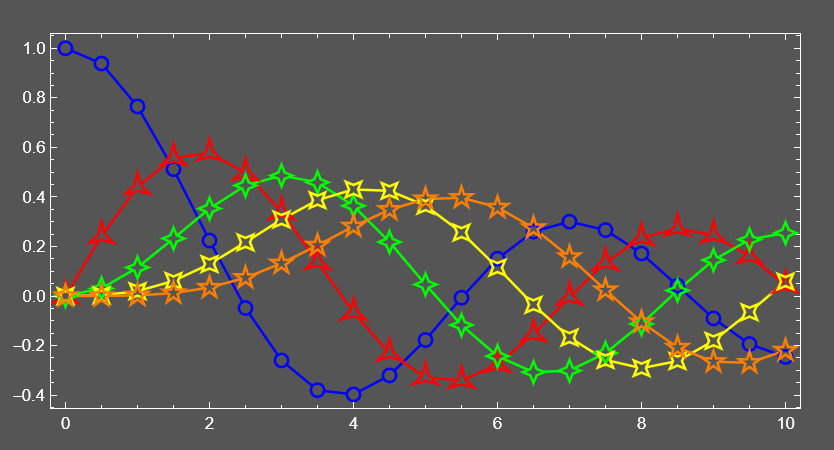
Construct a custom list plot where open plot markers have transparent faces for each other (but not for the lines):
data = Table[{x, BesselJ[k, x]}, {k, 0, 4}, {x, 0, 10, 0.5}];
markers = {"Circle", "ThreePointedStar", "FourPointedStar", "DiagonalFourPointedStar", "FivePointedStar"};
colors = {Blue, Red, Green, Yellow, Orange};
background = Darker@Gray;
Graphics[{Table[{colors[[i]], AbsoluteThickness[1.5], Line[data[[i]]], FaceForm[background], EdgeForm[None],
    PolygonMarker[markers[[i]], Offset[7], data[[i]]]}, {i, Length[data]}],
  Table[{FaceForm[None], EdgeForm[{colors[[i]], AbsoluteThickness[1.5], JoinForm["Miter"]}],
    PolygonMarker[markers[[i]], Offset[7], data[[i]]]}, {i, Length[data]}]}, AspectRatio -> 1/2, ImageSize -> 500,
 Frame -> True, Background -> background, FrameStyle -> White,
 ImagePadding -> {{30, 20}, {25, 20}}]
Neat Examples
Center markers which pick up PlotStyle and PlotTheme automatically:
cfm[name_String, size_ : 9] := Show[
   PolygonMarker[name, Offset@size, {FaceForm[White],
     Dynamic@EdgeForm[{CurrentValue["Color"], AbsoluteThickness[1], Opacity[1]}]}],
   PolygonMarker[name, Offset[size/2], EdgeForm[None]]];

data = Table[{x, BesselJ[k, x]}, {k, 0, 2}, {x, 0, 10, 0.5}];

ListPlot[data,
 PlotMarkers -> cfm /@ {"UpTriangle", "Square", "Circle"},
 Joined -> True, Frame -> True, Axes -> False, ImageSize -> 450,
 PlotRangePadding -> {Scaled[.05], Scaled[.1]},
 PlotLegends -> PointLegend[Automatic, LegendMarkerSize -> {40, 30}],
 ImageSize -> 450]
Half filled markers which pick up PlotStyle and PlotTheme automatically:
hfm1[name_String, size_ : 9] := Show[
   PolygonMarker[name, Offset@size, {FaceForm[White],
     Dynamic@EdgeForm[{CurrentValue["Color"], AbsoluteThickness[1], Opacity[1]}]}],
   PolygonMarker[name, Offset@size,
     EdgeForm[None]] /. {x_?Negative, y_?NumericQ} :> {0, y}];

data = Table[{x, BesselJ[k, x]}, {k, 0, 2}, {x, 0, 10, 0.5}];

ListPlot[data,
 PlotMarkers -> hfm1 /@ {"UpTriangle", "Square", "Circle"},
 Joined -> True, Frame -> True, Axes -> False, ImageSize -> 450,
 PlotRangePadding -> {Scaled[.05], Scaled[.1]},
 PlotLegends -> PointLegend[Automatic, LegendMarkerSize -> {40, 30}],
 ImageSize -> 450]
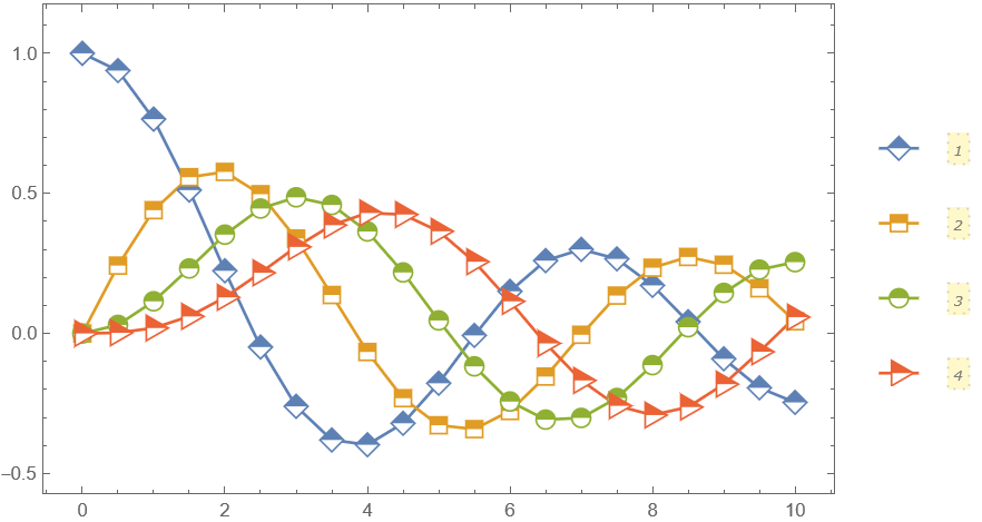
hfm2[name_String, size_ : 9] := Show[
   PolygonMarker[name, Offset@size, {
     FaceForm[White],
     Dynamic@EdgeForm[{CurrentValue["Color"], AbsoluteThickness[1], Opacity[1]}]}],
   Graphics[{EdgeForm[None],
     Replace[RegionDifference[PolygonMarker[name],
       Rectangle[{-10, -10}, {10, 0}]],
      p : {x_, y_} :> Offset[size p, {0, 0}], {-2}]}]];

data = Table[{x, BesselJ[k, x]}, {k, 0, 3}, {x, 0, 10, 0.5}];

ListPlot[data,
 PlotMarkers ->
  hfm2 /@ {"Diamond", "Square", "Circle", "RightTriangle"},
 Joined -> True, Frame -> True, Axes -> False, ImageSize -> 450,
 PlotRangePadding -> {Scaled[.05], Scaled[.1]},
 PlotLegends -> PointLegend[Automatic, LegendMarkerSize -> {40, 30}],
 ImageSize -> 450]
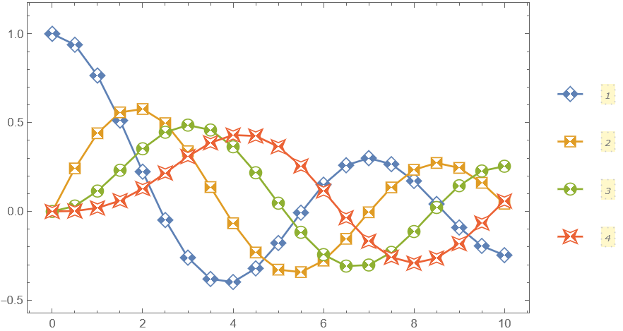
Contrast markers which pick up PlotStyle and PlotTheme automatically:
cfm2[name_String, size_ : 9] := Show[
   PolygonMarker[name, Offset@size, {
     FaceForm[White],
     Dynamic@EdgeForm[{CurrentValue["Color"], AbsoluteThickness[1], Opacity[1]}]}],
   Graphics[{EdgeForm[None],
     Replace[RegionDifference[
       RegionDifference[PolygonMarker[name],
        Triangle[{{-10, 10}, {10, 10}, {0, 0}}]],
       Triangle[{{-10, -10}, {10, -10}, {0, 0}}]],
      p : {x_, y_} :> Offset[size p, {0, 0}], {-2}]}]];

data = Table[{x, BesselJ[k, x]}, {k, 0, 3}, {x, 0, 10, 0.5}];

ListPlot[data,
 PlotMarkers ->
  cfm2 /@ {"Diamond", "Square", "Circle", "DiagonalFourPointedStar"},
 Joined -> True, Frame -> True, Axes -> False, ImageSize -> 450,
 PlotRangePadding -> {Scaled[.05], Scaled[.1]},
 PlotLegends -> PointLegend[Automatic, LegendMarkerSize -> {40, 30}], ImageSize -> 450]
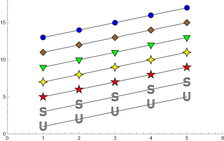
The package allows the usage of an arbitrary polygon as a plot marker. Here is an auxiliary function that converts a simple glyph into a set of points suitable for PolygonMarker:
pts[l_String] :=
  First[Cases[
    ImportString[
     ExportString[Style[l, FontFamily -> "Verdana", FontSize -> 20], "PDF"],
     If[$VersionNumber >= 12.2, {"PDF", "PageGraphics"}, {"PDF", "Pages"}]],
    c_FilledCurve :> c[[2, 1]], Infinity]];
(This conversion is approximate. If the precise conversion is needed one can apply one of the methods described in "How can I adaptively simplify a curved shape?")
An example of use:
ListPlot[ConstantArray[Range[5],7]+Range[0,12,2],PlotStyle->Gray,Joined->True,PlotMarkers->{PolygonMarker[pts["U"],Scaled[0.05],{FaceForm[LightBlue],EdgeForm[Black]}],
  PolygonMarker[pts["S"],Scaled[0.05],{FaceForm[LightBlue],EdgeForm[Black]}],
  PolygonMarker["FivePointedStar",Scaled[0.05],{FaceForm[Red],EdgeForm[Black]}],
  PolygonMarker["FourPointedStar",Scaled[0.05],{FaceForm[Yellow],EdgeForm[Black]}],
  PolygonMarker["DownTriangle",Scaled[0.05],{FaceForm[Green],EdgeForm[Black]}],
  PolygonMarker["DiagonalSquare",Scaled[0.05],{FaceForm[Brown],EdgeForm[Black]}],
  Graphics[{FaceForm[Blue],EdgeForm[Black],Disk[{0,0},Scaled[0.05/Sqrt[\[Pi]]]]}]},PlotRange->{{0,6},{0,18}},ImageSize->450]
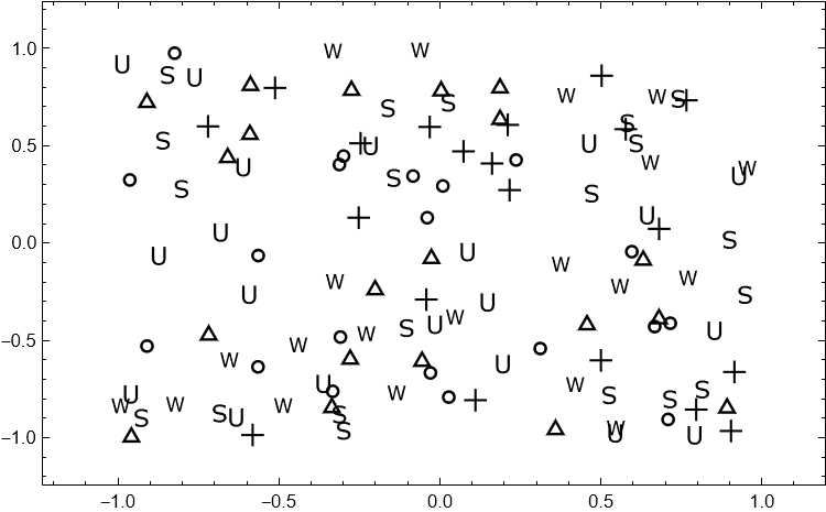
Here is an example of a black-and-white plot where the markers overlap considerably, I use here some of the symbols recommended by William Cleveland in his early works:
SeedRandom[11];
ListPlot[RandomReal[{-1,1},{6,20,2}],PlotMarkers->{
  PolygonMarker["Circle",Scaled[0.03],{FaceForm[None],EdgeForm[{Black,Thickness[.008]}]}],
  PolygonMarker["UpTriangle",Scaled[0.03],{FaceForm[None],EdgeForm[{Black,Thickness[.008]}]}],
  PolygonMarker["Cross",Scaled[0.03],{FaceForm[Black],EdgeForm[None]}],
  PolygonMarker[pts["U"],Scaled[0.03],{FaceForm[Black],EdgeForm[None]}],
  PolygonMarker["Sl",Scaled[0.03],{FaceForm[Black],EdgeForm[None]}],
  PolygonMarker[pts["W"],Scaled[0.03],{FaceForm[Black],EdgeForm[None]}]},
 Frame->True,FrameStyle->Black,Axes->False,PlotRangePadding->Scaled[.1],ImageSize->450]
Additional examples and explanations can be found in the following answers:
Plot markers where the boundary has the same hue as the body but is darker
Perfect vertical alignment of
PointLegendmarkers and their labelsHow to specify
PlotMarkersthat scale when graphic is resized?
The code of the package
BeginPackage["PolygonPlotMarkers`"];

ClearAll[PolygonMarker];
PolygonMarker::usage="\!\(\*RowBox[{\"PolygonMarker\", \"[\",StyleBox[\"\\\"\\!\\(\\*StyleBox[\\\"name\\\",\\\"TI\\\"]\\)\\\"\", ShowStringCharacters->True], \"]\"}]\) returns a unit area Polygon describing the shape \!\(\*StyleBox[\"\\\"\\!\\(\\*StyleBox[\\\"name\\\",\\\"TI\\\"]\\)\\\"\", ShowStringCharacters->True]\) with centroid at {0,0}.\n\!\(\*RowBox[{\"PolygonMarker\", \"[\", RowBox[{\"{\", RowBox[{SubscriptBox[StyleBox[\"p\", \"TI\"], StyleBox[\"1\", \"TR\"]], \",\", \ StyleBox[\"\[Ellipsis]\", \"TR\"], \",\", SubscriptBox[StyleBox[\"p\", \"TI\"], StyleBox[\"n\", \"TI\"]]}], \"}\"}], \"]\"}]\) returns a unit area Polygon with shape described by points \!\(\*SubscriptBox[StyleBox[\"p\", \"TI\"], StyleBox[\"i\", \"TI\"]]\) and centroid at {0,0}.\n\!\(\*RowBox[{\"PolygonMarker\", \"[\", RowBox[{StyleBox[\"shape\", \"TI\"], \",\", StyleBox[\"size\", \"TI\"]}], \"]\"}]\) returns Polygon of \!\(\*StyleBox[\"shape\", \"TI\"]\) with centroid at {0,0} and area \!\(\*SuperscriptBox[StyleBox[\"size\", \"TI\"], StyleBox[\"2\", \"TR\"]]\).\n\!\(\*RowBox[{\"PolygonMarker\", \"[\", RowBox[{StyleBox[\"shape\", \"TI\"], \",\", StyleBox[\"size\", \"TI\"], \",\", StyleBox[\"style\", \"TI\"]}], \"]\"}]\) returns a Graphics object which can be used as a marker for PlotMarkers where the style of \!\(\*StyleBox[\"shape\", \"TI\"]\) is defined by \!\(\*StyleBox[\"style\", \"TI\"]\).\n\!\(\*RowBox[{\"PolygonMarker\", \"[\",\"All\", \"]\"}]\) returns the list of names of predefined shapes.";
SyntaxInformation[PolygonMarker]={"ArgumentsPattern"->{_,_.,_.,OptionsPattern[]}};
PolygonMarker::nonsimple="The specified shape doesn't represent a simple polygon.";
Options[PolygonMarker] = {AlignmentPoint -> {0,0}, BaselinePosition -> Axis, AspectRatio -> Automatic, Axes -> False, AxesLabel -> None, AxesOrigin -> {0,0}, AxesStyle -> {}, Background -> None, BaseStyle -> {},  ContentSelectable -> Automatic, CoordinatesToolOptions -> Automatic, DisplayFunction :> Identity, Epilog -> {}, FormatType :> TraditionalForm, Frame -> False, FrameLabel -> None, FrameStyle -> {}, FrameTicks -> Automatic, FrameTicksStyle -> {}, GridLines -> None, GridLinesStyle -> {}, ImageMargins -> 0., ImagePadding -> All, ImageSize -> Automatic, ImageSizeRaw -> Automatic, LabelStyle -> {}, Method -> Automatic, PlotLabel -> None, PlotRange -> All, PlotRangeClipping -> False, PlotRangePadding -> Automatic, PlotRegion -> Automatic, PreserveImageOptions -> Automatic, Prolog -> {}, RotateLabel -> True, Ticks -> Automatic, TicksStyle -> {}};

Begin["`Private`"];

ClearAll[PolygonArea,PolygonCentroid,LineIntersectionPoint,ngon,nstar,ncross,scale,coords];
(*The shoelace method for computing the area of polygon http://mathematica.stackexchange.com/a/22587/280*)
PolygonArea[pts_?MatrixQ]:=Abs@Total[Det/@Partition[pts,2,1,1]]/2;
(*http://mathematica.stackexchange.com/a/7715/280*)
PolygonCentroid[pts_?MatrixQ]:=With[{dif=Map[Det,Partition[pts,2,1,{1,1}]]},ListConvolve[{{1,1}},Transpose[pts],{-1,-1}] . dif/(3 Total[dif])];
(*http://mathematica.stackexchange.com/a/51399/280*)
LineIntersectionPoint[{a_,b_},{c_,d_}]:=(Det[{a,b}] (c-d)-Det[{c,d}] (a-b))/Det[{a-b,c-d}];

ngon[n_,phase_:0]:=Table[{0,1} . RotationMatrix[2k Pi/n+phase],{k,0,n-1}];
(*
   nn - number of vertices in related polygram
   step - step at which vertices in the polygram are connected (must be lesser than nn/2)
   n - number of points in the final star (must be divisor of nn)  an illustration: http://en.wikipedia.org/wiki/Star_polygon#Simple_isotoxal_star_polygons
*)

nstar[n_/;n>=5,phase_:0]:=nstar[n,2,n,phase];
nstar[nn_,step_,n_,phase_:0]/;Divisible[nn,n]&&nn/2>step>nn/n:=Module[{a1,a2,b1,b2,ab},{a1,a2,b1,b2}=ngon[nn][[{1,1+step,1+nn/n,nn/n-step}]];
ab=LineIntersectionPoint[{a1,a2},{b1,b2}];
Flatten[Table[{a1,ab} . RotationMatrix[2k Pi/n+phase],{k,0,n-1}],1]];
(*a-semiwidths of the crossing stripes*)
ncross[n_,phase_:0,a_:1/10]:=Flatten[NestList[# . RotationMatrix[2Pi/n]&,{{-a,1},{a,1},{a,a Cot[Pi/n]}} . RotationMatrix[phase],n-1],1];

(*Unitizes the area of the polygon*)
scale[coords_]:=Chop[#/Sqrt@PolygonArea@#]&@N[coords,{18,18}];

coords["UpTriangle"|"Triangle"]=ngon[3]//scale;
coords["DownTriangle"]=ngon[3,Pi/3]//scale;
coords["LeftTriangle"]=ngon[3,Pi/6]//scale;
coords["RightTriangle"]=ngon[3,-Pi/6]//scale;
coords["ThreePointedStar"]=nstar[12,5,3]//scale;
coords["DiagonalSquare"|"Diamond"]=ngon[4,0]//scale;
coords["Square"]=ngon[4,Pi/4]//scale;
coords["FourPointedStar"]=nstar[8,3,4]//scale;
coords["DiagonalFourPointedStar"]=nstar[8,3,4,Pi/4]//scale;
coords["Pentagon"]=ngon[5]//scale;
coords["FivePointedStar"]=nstar[5]//scale;
coords["FivePointedStarThick"]=nstar[20,7,5]//scale;
coords["Hexagon"]=ngon[6]//scale;
coords["SixPointedStar"]=nstar[6]//scale;
coords["SixPointedStarSlim"]=nstar[12,5,6]//scale;
coords["SevenPointedStar"]=nstar[7]//scale;
coords["SevenPointedStarNeat"]=nstar[14,5,7]//scale;
coords["SevenPointedStarSlim"]=nstar[14,6,7]//scale;
coords["Cross"|"+"]=ncross[4]//scale;
coords["DiagonalCross"|"CrossDiagonal"|"X"|"x"]=ncross[4,Pi/4]//scale;
coords["TripleCross"|"TripleCrossUp"]=ncross[3]//scale;
coords["TripleCrossDown"|"Y"|"y"]=ncross[3,Pi/3]//scale;
coords["FivefoldCross"]=ncross[5]//scale;
coords["SixfoldCross"]=ncross[6]//scale;
coords["SevenfoldCross"]=ncross[7]//scale;
coords["EightfoldCross"]=ncross[8]//scale;
(*The truncated triangle shape originates from the Cross's Theorem http://demonstrations.wolfram.com/CrosssTheorem/*)
coords["UpTriangleTruncated"|"TriangleTruncated"|"TruncatedTriangle"]=Flatten[{{-3,6+Sqrt[3]},{3,6+Sqrt[3]}} . RotationMatrix[# Pi/3]&/@{0,2,4},1]//scale;
coords["DownTriangleTruncated"]=coords["UpTriangleTruncated"] . ReflectionMatrix[{0,1}];
coords["LeftTriangleTruncated"]=coords["UpTriangleTruncated"] . RotationMatrix[Pi/6];
coords["RightTriangleTruncated"]=coords["UpTriangleTruncated"] . RotationMatrix[-Pi/6];
(*Disk approximated by 24-gon*)
coords["Disk"|"Circle"]=ngon[24]//scale;

(*Plotting symbols recommended in[Cleveland W.S.The Elements of Graphing Data (1985)]*)
(*Symmetric symbol "H"*)
coords["H"]=Join[#,-#]&@Join[#,Reverse@# . {{1,0},{0,-1}}]&@{{333,108},{333,630},{585,630}}//scale;
(*Symmetric symbol "I"*)
coords["I"]=Join[#,-#]&@{{-20,-68},{-64,-68},{-64,-104},{64,-104},{64,-68},{20,-68}}//scale;
(*Antisymmetric symbol "N"*)
coords["N"]=Join[#,-#]&@{{18,-32},{30,-32},{30,32},{17,32},{17,-12}}//scale;
(*Antisymmetric symbol "Z"*)
coords["Z"]=Join[#,-#]&@{{-567,-432},{-567,-630},{567,-630},{567,-414},{-234,-414}}//scale;
(*Antisymmetric symbol "S" (simple)*)
coords["S"]=Join[#,-#]&@{{-176,-54},{116,-54},{167,-100},{167,-170},{116,-216},{-284,-216},{-284,-324},{176,-324},{293,-216},{293,-54}}//scale;
(*Antisymmetric symbol "S" (curved,long)*)
coords["LongS"|"SLong"|"Sl"]=Join[#,-#]&@{{-(49/16),-(3/11)},{-(425/91),23/28},{-(141/26),31/12},{-(165/32),88/19},{-(167/45),106/17},{-(24/17),149/21},{121/69,233/33},{130/27,31/5},{130/27,118/29},{127/47,199/39},{7/20,233/42},{-(12/7),139/26},{-(65/21),139/31},{-(395/113),114/35},{-(157/52),77/39},{-(83/44),56/41},{9/22,39/43}}//scale;
(*Antisymmetric symbol "S" (curved,wide)*)
coords["WideS"|"SWide"|"Sw"]=Join[#,-#]&@{{80/11,-(3/5)},{49/6,-(9/4)},{97/12,-(41/11)},{39/5,-(35/8)},{88/13,-(65/12)},{51/10,-(49/8)},{2,-(13/2)},{-(20/11),-(13/2)},{-(37/8),-(81/13)},{-(81/13),-(40/7)},{-(59/8),-(54/11)},{-(81/10),-(26/7)},{-(70/11),-(29/9)},{-(57/11),-(46/11)},{-(11/4),-(33/7)},{11/7,-(19/4)},{16/3,-(37/9)},{31/5,-(38/11)},{32/5,-(38/13)},{37/6,-(49/24)},{61/13,-(6/5)},{23/7,-(13/14)},{-(25/9),-(4/5)},{-(23/4),-(3/13)}}//scale;

PolygonMarker[name_String]:=Polygon[coords[name]];
PolygonMarker[name_String,size_?NumericQ]:=Polygon[size coords[name]];
PolygonMarker[name_String,(h:Scaled|Offset)[size_?NumericQ]]:=Polygon[h[size #,{0,0}]&/@coords[name]];
PolygonMarker[coords:{{_?NumericQ,_?NumericQ}..},size_?NumericQ]:=Polygon[size N[scale[Transpose[Transpose[coords]-PolygonCentroid[coords]]],{16,16}]];
PolygonMarker[coords:{{_?NumericQ,_?NumericQ}..},Scaled[size_?NumericQ]]:=Polygon[Scaled[size #,{0,0}]&/@N[scale[Transpose[Transpose[coords]-PolygonCentroid[coords]]],{16,16}]];
PolygonMarker[arg:_String|{{_?NumericQ,_?NumericQ}..},size:_?NumericQ|(Scaled|Offset)[_?NumericQ],positions:{_?NumericQ,_?NumericQ}|{{_?NumericQ,_?NumericQ}..}]:=Translate[PolygonMarker[arg,size],positions];
PolygonMarker[]=PolygonMarker[All]={"TripleCross","Y","UpTriangle","UpTriangleTruncated","DownTriangle","DownTriangleTruncated","LeftTriangle","LeftTriangleTruncated","RightTriangle","RightTriangleTruncated","ThreePointedStar","Cross","DiagonalCross","Diamond","Square","FourPointedStar","DiagonalFourPointedStar","FivefoldCross","Pentagon","FivePointedStar","FivePointedStarThick","SixfoldCross","Hexagon","SixPointedStar","SixPointedStarSlim","SevenfoldCross","SevenPointedStar","SevenPointedStarNeat","SevenPointedStarSlim","EightfoldCross","Disk","H","I","N","Z","S","Sw","Sl"};
(*A subset of plot markers suitable for use when plotting symbols on the plot significantly overlap.*)
PolygonMarker["Overlap"]={"TripleCross","Y","UpTriangle","DownTriangle","LeftTriangle","RightTriangle","ThreePointedStar","Cross","DiagonalCross","Diamond","Square","FourPointedStar","DiagonalFourPointedStar","FivefoldCross","FivePointedStar","FivePointedStarThick","Disk","H","I","N","Z","S","Sw","Sl"};
(* Generate a Graphics object which can be used as a marker for PlotMarkers *)
PolygonMarker[shape_,size_,g_]:=PolygonMarker[shape,size,{g}];
PolygonMarker[shape_,size_,{g___}]:=Block[{p=PolygonMarker[shape,size]},Graphics[{g,p},AlignmentPoint->{0,0},ImagePadding->All,PlotRange->All]/;Head[p]===Polygon];
(* This form allows to construct composite plot markers containing additional graphics primitives *)
PolygonMarker[shape_,size_,{{g___},{primitives___}}]:=Block[{p=PolygonMarker[shape,size]},Graphics[{{g,p},{primitives}},AlignmentPoint->{0,0},ImagePadding->All,PlotRange->All]/;Head[p]===Polygon];
(* This form allows to pass any Graphics options as an argument of PolygonMarker *)
PolygonMarker[shape_,size_,style_,opts:OptionsPattern[]]:=Block[{gr=PolygonMarker[shape,size,style]},Show[gr,opts]/;Head[gr]===Graphics];

End[];

EndPackage[];


