27
$\begingroup$

I saw in this question that Mathematica can draw spherical triangles. I guess something similar can be done to plot a spherical polygon. I am interested in something similar:

I have a set of points on a sphere, as well as a set of edges connecting them (the edges are spherical geodesics). I would like to plot the corresponding partition, and to fill each spherical polygon with a different color. How can this be done?

Here is an example. The lines in the matrix $P$ are the coordinates of the points, the edges are represented in $E$ (indices represent points in the lines of $P$), and the faces are represented in $F$.

$$P = \begin{pmatrix} -0.9207 & -0.3896 & 0.0091 \\ -0.8272 & 0.5077 & -0.2399 \\ 0.2544 & -0.3511 & 0.9010 \\ 0.3510 & 0.6527 & 0.6712 \\ 0.5436 & -0.6326 & -0.5513 \\ 0.6016 & 0.2317 & -0.7643 \end{pmatrix}$$

$$ E = \begin{pmatrix} 1 & 2\\ 1 & 3 \\ 1 & 5 \\ 2 & 4 \\ 2 & 6 \\ 3 & 4\\ 3 & 5\\ 4 & 6\\ 5 & 6 \end{pmatrix}$$

$$ F = (1,3,5);(1,2,4,3);(1,2,6,5);(3,4,6,5);(2,4,6)$$

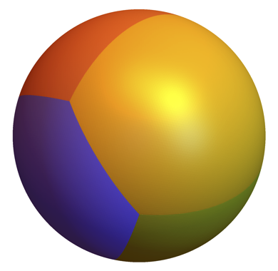
In the meantime, I found a Matlab solution using geom3d. Here is the output:

enter image description here

$\endgroup$
2
  • $\begingroup$ What coordinate system is each line of $P$ in? The sphere is a unit sphere? $\endgroup$
    – Taiki
    Commented Apr 1, 2015 at 10:07
  • $\begingroup$ Yes, it is a unit sphere. The sum of squares of the coordinates is roughly equal to one. $\endgroup$ Commented Apr 1, 2015 at 10:16

5 Answers 5

25
$\begingroup$

A crude attempt

This is for Mathematica 10+ only. To construct each face, I use an intersection between a unit 3-ball centred at the origin and a pyramid whose base is at infinity and apex is at the origin. Each edge of the pyramid passes through each vertex of the spherical face.

The pyramid is given by ConicHullRegion[{origin}, {vertices}]. The intersection is found by RegionIntersection, whose boundary is then discretised for display.

origin = {0, 0, 0};
points = {
  {-0.9207, -0.3896, 0.0091},
  {-0.8272,  0.5077, -0.2399},
  {0.2544, -0.3511, 0.901},
  {0.351, 0.6527, 0.6712},
  {0.5436, -0.6326, -0.5513},
  {0.6016, 0.2317, -0.7643}
};
fs = {{1, 3, 5}, {1, 2, 4, 3}, {1, 2, 6, 5}, {3, 4, 6, 5}, {2, 4, 6}};
faces = points[[#]] & /@ fs;
colours = RandomColor[5];
composite = BoundaryDiscretizeRegion[
  RegionIntersection[
    ConicHullRegion[{origin}, #],
    Ball[origin]
  ]
] & /@ faces;
Show@MapThread[
  HighlightMesh[
    #1,
    {Style[1, None], Style[2, Specularity[GrayLevel[0.6], 50], #2]}
  ] &,
  {composite, colours}
]

Broken Sphere

The option MaxCellMeasure doesn't seem to work in BoundaryDiscretizeRegion for some mysterious reason...

A finer attempt

With some helper functions, one of which is adapted from ark in #23053, I fill up the cracks by adding points along the edges directly to the mesh of each face.

(For Mathematica 10.1, you can use the newly introduced Subdivide in lieu of finddiv.)

arcinterior[{r1_, r2_}, nt_] := Table[
  RotationTransform[t VectorAngle[r1, r2], Cross[r1, r2]][r1],
  {t, Most@Rest@finddiv[0, 1, nt]}
];
finddiv[imin_, imax_, divs_] := With[
  {di = (imax - imin)/(divs - 1)},
  Range[imin, imax, di]
];
fbs = Partition[Append[#, First@#], 2, 1] & /@ fs;
faceboundaries = Map[points[[#]] &, fbs, {3}];
slicings = 20;
fbsliced = MapThread[
  Join,
  {
    Flatten[#, 1] & /@ (
      Function[twopts, arcinterior[twopts, slicings]] /@ # & /@ faceboundaries
    ),
    faces
  }
];
refinedcomposite = MapThread[
  ConvexHullMesh[Level[MeshPrimitives[#1, 0], {2}]~Join~#2] &,
  {composite, fbsliced}
];
Show@MapThread[
  HighlightMesh[
    #1,
    {Style[1, None], Style[2, Specularity[GrayLevel[0.6], 50], #2]}
  ] &,
  {refinedcomposite, colours}
]

Refined Broken Sphere

Unlike 2012rcampion's solution, there're no open seams to be seen. The next problem would be to make a finer surface mesh somehow...

The final attempt

As BoundaryDiscretizeRegion can't be asked to discretise the spherical faces with a finer mesh, I get the mesh from a discretised unit 2-sphere directly and use the region from RegionIntersection to filter out unwanted vertices.

The higher the value of maxcellarea, the smoother the surface but also the slower the filtering (i.e. the evaluation of actualfaces).

slicings above may need to be increased; 50 is nice.

precomposite = RegionIntersection[
  ConicHullRegion[{origin}, #],
  Ball[origin]
] & /@ faces;
maxcellarea = 1/100000;
spherepts = Level[
  MeshPrimitives[DiscretizeGraphics[Sphere[], MaxCellMeasure -> maxcellarea], 0],
  {-2}
];
actualfaces = Select[
  spherepts,
  Function[elem, RegionMember[#, elem]]
] & /@ precomposite;
smoothcomposite = ConvexHullMesh /@ Catenate /@ Transpose[
  {actualfaces, fbsliced, ConstantArray[{origin}, Length@fs]}
];
ball = MapThread[
  {EdgeForm[], Specularity[GrayLevel[0.6], 50], #2, MeshPrimitives[#1, 2]} &,
  {smoothcomposite, colours}
];
Graphics3D[ball, Boxed -> False]

Smooth Ball

As pointed out by Michael E2 in his answer, faceted shading can be removed by VertexNormals. The helper function anglesign below is also suggested by him in #79604.

anglesign[v1_, v2_] := Sign@Det@Prepend[Differences@v1, v2];
ball = MapThread[
  {EdgeForm[], #2, MeshPrimitives[#1, 2]} &,
  {smoothcomposite, colours}
] /. Polygon[vs_] :> Polygon[
  vs,
  VertexNormals -> (anglesign[vs, #] # &) /@ vs
];
Graphics3D[ball, Boxed -> False]

With just maxcellarea = 1/1000:

smooth ball

Decrease maxcellarea to smoothen the boundary (and specularity if added).

Putting it all together

Let me put all parts of the code together here:

(* the givens *)

points = {
  {-0.9207, -0.3896, 0.0091},
  {-0.8272,  0.5077, -0.2399},
  {0.2544, -0.3511, 0.901},
  {0.351, 0.6527, 0.6712},
  {0.5436, -0.6326, -0.5513},
  {0.6016, 0.2317, -0.7643}
};
fs = {{1, 3, 5}, {1, 2, 4, 3}, {1, 2, 6, 5}, {3, 4, 6, 5}, {2, 4, 6}};

(* helper functions *)

arcinterior[{r1_, r2_}, nt_] := Table[
  RotationTransform[t VectorAngle[r1, r2], Cross[r1, r2]][r1],
  {t, Most@Rest@finddiv[0, 1, nt]}
];
finddiv[imin_, imax_, divs_] := With[
  {di = (imax - imin)/(divs - 1)},
  Range[imin, imax, di]
];

(* settings *)

origin = {0, 0, 0};
slicings = 50 (* the higher the smoother the seams *);
maxcellarea = 1/100000 (* the lower the smoother the surface *);
colours = RandomColor[5];

(* points along the edges of the faces *)

faces = points[[#]] & /@ fs;
fbs = Partition[Append[#, First@#], 2, 1] & /@ fs;
faceboundaries = Map[points[[#]] &, fbs, {3}];
fbsliced = MapThread[
  Join,
  {
    Flatten[#, 1] & /@ (
      Function[twopts, arcinterior[twopts, slicings]] /@ # & /@ faceboundaries
    ),
    faces
  }
];

(* points on the faces *)

precomposite = RegionIntersection[
  ConicHullRegion[{origin}, #],
  Ball[origin]
] & /@ faces;
spherepts = Level[
  MeshPrimitives[DiscretizeGraphics[Sphere[], MaxCellMeasure -> maxcellarea], 0],
  {-2}
];
actualfaces = Select[
  spherepts,
  Function[elem, RegionMember[#, elem]]
] & /@ precomposite;

(* putting the faces together and colouring them *)

smoothcomposite = ConvexHullMesh /@ Catenate /@ Transpose[
  {actualfaces, fbsliced, ConstantArray[{origin}, Length@fs]}
];
ball = MapThread[
  {EdgeForm[], Specularity[GrayLevel[0.6], 50], #2, MeshPrimitives[#1, 2]} &,
  {smoothcomposite, colours}
];
Graphics3D[ball, Boxed -> False]

Let me wrap up my answer with a spinning ball:

Spinning Ball

Or perhaps this...

Pulsing Ball

centroids = RegionCentroid /@ precomposite;
pulser = Table[
  Graphics3D[
    MapThread[Translate[#1, #2/i] &, {ball, centroids}],
    Boxed -> False
  ],
  {i, {Infinity, 20, 10, 8, 6, 4, 6, 8, 10, 20}}
];
ListAnimate[pulser, AnimationRate -> 10]
$\endgroup$
6
  • $\begingroup$ ps is not defined, did you mean points? $\endgroup$ Commented Apr 1, 2015 at 12:53
  • $\begingroup$ Oh yes. Thanks. Edited. $\endgroup$
    – Taiki
    Commented Apr 1, 2015 at 13:08
  • 2
    $\begingroup$ Great answer. The last view of the slices is particularly interesting :) $\endgroup$ Commented Apr 2, 2015 at 8:37
  • 1
    $\begingroup$ All the answer posted are very good. I'll accept yours because of the slices picture :) $\endgroup$ Commented Apr 4, 2015 at 11:48
  • 1
    $\begingroup$ The solutions are great, my compliments. $\endgroup$
    – Narasimham
    Commented Apr 6, 2015 at 3:42
18
$\begingroup$

Using the same initialization code as Taiki:

origin = {0, 0, 0};
points = {{-0.9207, -0.3896, 0.0091}, {-0.8272, 
    0.5077, -0.2399}, {0.2544, -0.3511, 0.901}, {0.351, 0.6527, 
    0.6712}, {0.5436, -0.6326, -0.5513}, {0.6016, 0.2317, -0.7643}};
fs = {{1, 3, 5}, {1, 2, 4, 3}, {1, 2, 6, 5}, {3, 4, 6, 5}, {2, 4, 6}};
faces = points[[#]] & /@ fs;

Then we split each face into triangles radiating from the first point in the polygon:

triangles = (Prepend[First[#]] /@ Partition[Rest[#], 2, 1]) & /@ faces

(You need v10 for the operator form of Prepend, otherwise just make it a function.)

Generate some random colors for the faces:

colors = Table[
  ConstantArray[
   Hue[i/Length[triangles]], {Length[triangles[[i]]]}], {i, 
   Length[triangles]}]

Finally use ParametricPlot to generate the actual sphere, by linearly interpolating to draw the polygons, then normalizing the resulting vectors:

ParametricPlot3D[
 Evaluate[Normalize[#1 + (#2 - #1) u + (#3 - #1) v] & @@@ 
   Join @@ triangles], {u, 0, 1}, {v, 0, 1 - u}, 
 PlotStyle -> Flatten[colors], Mesh -> None]

Still needs a lot of work, for example you can see the seams where the triangles are meshed together.

enter image description here

$\endgroup$
0
17
$\begingroup$

What about some 2D Geo functionality for this?

points = {{-0.9207, -0.3896, 0.0091}, {-0.8272, 0.5077, -0.2399}, {0.2544, -0.3511, 0.9010}, {0.3510, 0.6527, 0.6712}, {0.5436, -0.6326, -0.5513}, {0.6016, 0.2317, -0.7643}};
edges = {{1, 2}, {1, 3}, {1, 5}, {2, 4}, {2, 6}, {3, 4}, {3, 5}, {4, 6}, {5, 6}};

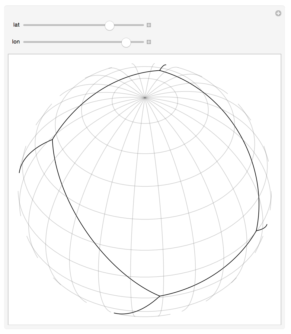
Construct the geodesics as GeoPath objects:

latlons = First@GeoPosition[GeoPositionXYZ[points, 1]];
geodesics = {GeoPath[latlons[[#]]]} & /@ edges;

Then use the "Orthographic" projection to represent the result:

Manipulate[GeoGraphics[geodesics, GeoProjection -> {"Orthographic", "Centering" -> {lat, lon}}, GeoGridLines -> Quantity[15, "AngularDegrees"], GeoRange -> {{-90, 90}, {-180, 180} + lon}, GeoBackground -> None], {{lat, 0}, -90, 90}, {{lon, 0}, -180, 180}]

enter image description here You may even use a map for reference, and use any other projection. With "LambertAzimuthal" you see the whole sphere at once:

GeoGraphics[geodesics, GeoProjection -> "LambertAzimuthal", GeoRange -> "World", GeoGridLines -> Quantity[15, "AngularDegrees"], GeoCenter -> -100]

enter image description here

$\endgroup$
2
  • $\begingroup$ It would be nice if you could also add how we could colour each face. $\endgroup$
    – Taiki
    Commented Apr 2, 2015 at 17:44
  • $\begingroup$ @Taiki: That was exactly what I was thinking :) $\endgroup$ Commented Apr 4, 2015 at 11:47
16
$\begingroup$

Let me add another answer. This code is much shorter and faster than my previous one, and the resulting mesh of each face is much cleaner.

The procedure is simple. Triangles are first made from the given face vertices and discretised. Each mesh point is then pushed onto a 2-sphere while its angular positions are maintained.

points = {
  {-0.9207, -0.3896, 0.0091},
  {-0.8272,  0.5077, -0.2399},
  {0.2544, -0.3511, 0.901},
  {0.351, 0.6527, 0.6712},
  {0.5436, -0.6326, -0.5513},
  {0.6016, 0.2317, -0.7643}
};
fs = {{1, 3, 5}, {1, 2, 4, 3}, {1, 2, 6, 5}, {3, 4, 6, 5}, {2, 4, 6}};
colours = RandomColor[Length@fs];
tospherical = CoordinateTransformData["Cartesian" -> "Spherical", "Mapping"];
tocartesian = CoordinateTransformData["Spherical" -> "Cartesian", "Mapping"];
maxcellarea = 1 / 100;
faces = Map[tocartesian, #, {-2}] &[
  Map[ReplacePart[tospherical[#], 1 -> 1] &, #, {-2}] &[
    (MeshPrimitives[#, 2] &) /@
      (DiscretizeRegion[#, MaxCellMeasure -> maxcellarea] &) /@
        Polygon /@ (points[[#]] &) /@ fs
  ]
];
display[f_] := Graphics3D[
  MapThread[
    {EdgeForm[], Specularity[GrayLevel[0.6], 50], #2, #1} &,
    {f, colours}
  ],
  Boxed -> False
];
display[faces]

With maxcellarea = 1/100:

rough ball

With maxcellarea = 1/1000000:

fine ball

As pointed out by Michael E2 in his answer, faceted shading can be removed by VertexNormals. The helper function anglesign below is also suggested by him in #79604.

anglesign[v1_, v2_] := Sign@Det@Prepend[Differences@v1, v2];
displaysmooth[f_] := Graphics3D[
  MapThread[
    {EdgeForm[], #2, #1} &,
    {f, colours}
  ] /. Polygon[vs_] :> Polygon[
    vs,
    VertexNormals -> (anglesign[vs, #] # &) /@ vs
  ],
  Boxed -> False
];

With just maxcellarea = 1/1000, displaysmooth[faces] gives

fine ball as well

Decrease maxcellarea to smoothen the boundary (and specularity if added).

The sphere-splitting procedure can be visualised as inflating a prism balloon:

spinning inflating ball

Each inflating state can be generated by varying mod between 0 to 1 in:

prefaces = Map[tospherical, #, {-2}] &[
  (MeshPrimitives[#, 2] &) /@
    (DiscretizeRegion[#, MaxCellMeasure -> maxcellarea] &) /@
      Polygon /@ (points[[#]] &) /@ fs
];
modfaces[mod_] := Map[tocartesian, #, {-2}] &[
  Map[
    ReplacePart[#, 1 -> #[[1]] + mod (1 - #[[1]])] &,
    prefaces,
    {-2}
  ]
];
display[modfaces[1/2]] (* for example *)

What if mod > 1?

display[modfaces[7]]

bulbous ball

Let's get artistic!

By tinkering with the inside of ReplacePart in modfaces we can get some interesting deformations of the ball.

modfaces[mod_] := Map[tocartesian, #, {-2}] &[
  Map[
    ReplacePart[
      #,
      1 -> 1 - mod Min[
        Function[point, EuclideanDistance[point, tocartesian@#]] /@ points
      ]
    ] &,
    prefaces,
    {-2}
  ]
];
display[modfaces[1]]

flowery ball

modfaces[mod_] := Map[tocartesian, #, {-2}] &[
  Map[
    ReplacePart[
      #,
      1 -> 1 - mod Sin@Max[
        Function[point, CosineDistance[point, tocartesian@#]] /@ points
      ]
    ] &,
    prefaces,
    {-2}
  ]
];
display[modfaces[1]]

clubby balls

The possibilities are endless!

Growing faces

points = {
  {-0.9207, -0.3896, 0.0091},
  {-0.8272,  0.5077, -0.2399},
  {0.2544, -0.3511, 0.901},
  {0.351, 0.6527, 0.6712},
  {0.5436, -0.6326, -0.5513},
  {0.6016, 0.2317, -0.7643}
};
fs = {{1, 3, 5}, {1, 2, 4, 3}, {1, 2, 6, 5}, {3, 4, 6, 5}, {2, 4, 6}};
colours = RandomColor[Length@fs];
tospherical = CoordinateTransformData["Cartesian" -> "Spherical", "Mapping"];
tocartesian = CoordinateTransformData["Spherical" -> "Cartesian", "Mapping"];
maxcellarea = 1 / 100000;

(* push the given points to really be on the sphere *)
points = tocartesian /@ (ReplacePart[tospherical[#], 1 -> 1] &) /@ points;

fbs = Partition[Append[#, First@#], 2, 1] & /@ fs;
faceboundaries = Map[points[[#]] &, fbs, {3}];
facevertices = points[[#]] & /@ fs;
flatfaces = Polygon /@ facevertices;

(* tangent plane to a point on a sphere *)
infplane[cartpt_] := With[
  {threepts = FindInstance[{x, y, z}.cartpt == 0, {x, y, z}, Reals, 3]},
  InfinitePlane[TranslationTransform[cartpt][{x, y, z} /. threepts]]
];

smallfaces[border_] := (
  smallfacevertices = MapThread[
    Function[
      {fv, fbound},
      TranslationTransform[
        Module[
          {
            vertex, twoedges, othervertices,
            plane, ovpop, vector1, vector2, theta, vertexdisplacement
          },
          vertex = #;           
          twoedges = Select[fbound, Function[x, MemberQ[x, vertex]]];
          othervertices = Complement[Union @@ twoedges, {vertex}];
          plane = infplane[vertex];
          (* ovpop: other vertices projected on the plane *)
          ovpop = RegionNearest[plane, #] & /@ othervertices;
          vector1 = -vertex + ovpop[[1]];
          vector2 = -vertex + ovpop[[2]];
          theta = VectorAngle[vector1, vector2];
          vertexdisplacement = (border / 2) / Sin[theta / 2];
          vertexdisplacement Normalize[Normalize[vector1] + Normalize[vector2]]
        ]
      ][#] & /@ fv
    ],
    {facevertices, faceboundaries}
  ];
  smallflatfaces = Polygon /@ smallfacevertices;
  ff = DiscretizeRegion[#, MaxCellMeasure -> maxcellarea] & /@ smallflatfaces;
  ffpolygons = MeshPrimitives[#, 2] & /@ ff;
  sfpolygons = Map[ReplacePart[tospherical[#], 1 -> 1] &, ffpolygons, {-2}];
  Map[tocartesian, sfpolygons, {-2}]
);

display[f_] := Graphics3D[
  MapThread[
    {EdgeForm[], Specularity[GrayLevel[0.6], 50], #2, #1} &,
    {f, colours}
  ],
  Boxed -> False
];
display[smallfaces[1 / 20]]

growing faces

Each frame is given by display[smallfaces[x]] where x corresponds to the width of the gap.

Reinforcement

So far I haven't made use of the given edges. Now is the time.

In case one fears the faces will fall apart, let me add some reinforcing fasteners.

(For Mathematica 10.1, you can use the newly introduced Subdivide in lieu of finddiv.)

(* given edges *)

es = {{1, 2}, {1, 3}, {1, 5}, {2, 4}, {2, 6}, {3, 4}, {3, 5}, {4, 6}, {5, 6}};

(* helper functions *)

arcinterior[{r1_, r2_}, nt_] := Table[
  RotationTransform[t VectorAngle[r1, r2], Cross[r1, r2]][r1],
  {t, finddiv[0, 1, nt]}
];
finddiv[imin_, imax_, divs_] := With[
  {di = (imax - imin)/(divs - 1)},
  Range[imin, imax, di]
];
infplane[cartpt_] := With[
  {threepts = FindInstance[{x, y, z}.cartpt == 0, {x, y, z}, Reals, 3]},
  InfinitePlane[TranslationTransform[cartpt][{x, y, z} /. threepts]]
];

(* set-up *)

origin = {0, 0, 0};
stripwidth = 0.1;
protrusion = 1.04;
pointyend = 1.08;
pointsfar = tocartesian /@ (ReplacePart[tospherical[#], 1 -> protrusion] &) /@ points;
edgevertices = pointsfar[[#]] & /@ es;
slicingsizes = Floor[(EuclideanDistance @@@ edgevertices) / stripwidth];
edgesliced = MapThread[arcinterior[#1, #2] &, {edgevertices, slicingsizes}];

(* constructing reinforcement *)

step1 = Partition[#, 2, 1] & /@ edgesliced;
step2 = (FindInstance[
  RegionMember[infplane[#[[1]]], {x, y, z}] &&
    RegionMember[infplane[#[[2]]], {x, y, z}] &&
    EuclideanDistance[{x, y, z}, #[[1]]] == stripwidth,
  {x, y, z},
  Reals,
  2
] &) /@ # & /@ step1;
step3 = Partition[#, 2, 1] & /@ step2;
step4 = (Module[
  {center, pts},
  pts = {x, y, z} /. Join[#[[1]], #[[2]]];
  center = Mean[pts];
  SortBy[pts, (N[ArcTan @@ Rest[# - center]] &)]
] &) /@ # & /@ step3;
pyramids = (Pyramid[Append[#, origin]] &) /@ # & /@ step4;
pricks = (Pyramid[
    Append[#, tocartesian[
      ReplacePart[tospherical[Mean[#]], 1 -> pointyend]]]
    ] &
  ) /@ # & /@ step4;
reinf = Graphics3D[{
  {EdgeForm[], GrayLevel[0.3], Specularity[GrayLevel[0.6], 50], pyramids, pricks},
  {
    Specularity[GrayLevel[0.6], 50],
    GrayLevel[0.3],
    Sphere[
      #,
      Sqrt[2] EuclideanDistance @@ ({x, y, z} /. step2[[1, 1]]) / 2
    ] & /@ pointsfar
  }
}];
Show[{display[faces], reinf}]

precious ball

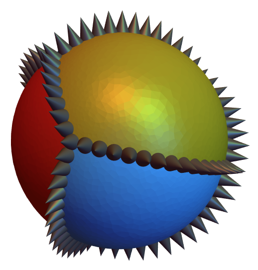
Or the following for its own dramatic protection:

rootpos = 0.99;
roots = tocartesian /@ (ReplacePart[tospherical[#], 1 -> rootpos] &) /@ points;
edgevertices = roots[[#]] & /@ es;
edgesliced = MapThread[arcinterior[#1, #2] &, {edgevertices, slicingsizes}];
cones = Cone[
  {#, tocartesian[ReplacePart[tospherical[#], 1 -> pointyend]]},
  Sqrt[2] stripwidth/2
] & /@ (Union @@ edgesliced);
prickles = Graphics3D[{
  EdgeForm[],
  GrayLevel[0.3],
  Specularity[GrayLevel[0.6], 50],
  cones
}];
Show[{display[faces], prickles}]
pointy ball

I shall now stop!

$\endgroup$
3
  • 3
    $\begingroup$ This reminds me of a screensaver I had on my Windows 98 computer =) $\endgroup$ Commented Apr 6, 2015 at 2:04
  • 2
    $\begingroup$ The reinforcement picture is way too cool :)) $\endgroup$ Commented Apr 7, 2015 at 12:35
  • $\begingroup$ I've made the reinforcing belt prettier, as well as giving the ball some offensive ability. $\endgroup$
    – Taiki
    Commented Apr 8, 2015 at 18:04
11
$\begingroup$

An FEM element-meshing approach. The quality is controlled by the option "MaxCellMeasure" -> {"Length" -> 0.05}. Note that the VertexNormals -> -coords option causes the polygonal sphere to be smoothed out when displayed on the screen.

Needs["NDSolve`FEM`"];
points = {{-0.9207, -0.3896, 0.0091}, {-0.8272, 
    0.5077, -0.2399}, {0.2544, -0.3511, 0.901}, {0.351, 0.6527, 
    0.6712}, {0.5436, -0.6326, -0.5513}, {0.6016, 0.2317, -0.7643}};
fs = {{1, 3, 5}, {1, 2, 4, 3}, {1, 2, 6, 5}, {3, 4, 6, 5}, {2, 4, 6}};

bmesh = ToBoundaryMesh[
   "Coordinates" -> points,
   "BoundaryElements" -> MapIndexed[
     Function[{face, index},
      With[{tri = Partition[Rest[face], 2, 1]},
       TriangleElement[Join[{First[face]}, #] & /@ tri, 
        Table[First@index, {Length@tri}]]]],
     fs],
   "MeshOrder" -> 1
   ];
emesh = ToElementMesh[bmesh,
   "MaxCellMeasure" -> {"Length" -> 0.05}];

With[{boundary = ToBoundaryMesh[emesh]},
  coords = Normalize /@ boundary["Coordinates"];
  sphmesh = ToBoundaryMesh[
    "Coordinates" -> coords,
    "BoundaryElements" -> boundary["BoundaryElements"]
    ]];
Graphics3D[
 ElementMeshToGraphicsComplex[sphmesh,
  All,
  "MeshElementStyle" -> 
   Table[Directive[EdgeForm[], ColorData[97, c]], {c, 5}],
  VertexNormals -> -coords
  ]
 ]

Mathematica graphics

$\endgroup$

Your Answer

By clicking “Post Your Answer”, you agree to our terms of service and acknowledge you have read our privacy policy.

Not the answer you're looking for? Browse other questions tagged or ask your own question.