14
$\begingroup$

I am using Cylinder to produce wide flat disks (in Mathematica 8). This works just fine except that the circular base of such a cylinder turns out to be really just a 40-gon which is simply too coarse an approximation to a circle for what I have in mind. Is there a way to convince Mathematica to use say a 200-gon as a circular base for a cylinder?

Here is an example of the kind of picture that I am trying to create. Zoom in to see how coarse the cylinders' curved surfaces pan out.

Graphics3D[{Cylinder[{{0, 0, 0}, 0.0011 {0.`, 0.`, -0.9510565162951536`}}, .1], 
  Cylinder[{{0, 0, 0}, 0.0011 {0.`, 0.`, 0.9510565162951536`}}, .1], 
  Cylinder[{{0, 0, 0}, 
    0.0011 {-0.85065080835204`, 0.`, -0.42532540417601994`}}, .1], 
  Cylinder[{{0, 0, 0}, 
    0.0011 {0.85065080835204`, 0.`, 0.42532540417601994`}}, .1], 
  Cylinder[{{0, 0, 0}, 
    0.0011 {0.6881909602355868`, -0.5`, -0.42532540417601994`}}, .1], 
  Cylinder[{{0, 0, 0}, 
    0.0011 {0.6881909602355868`, 0.5`, -0.42532540417601994`}}, .1], 
  Cylinder[{{0, 0, 0}, 
    0.0011 {-0.6881909602355868`, -0.5`, 0.42532540417601994`}}, .1], 
  Cylinder[{{0, 0, 0}, 
    0.0011 {-0.6881909602355868`, 0.5`, 0.42532540417601994`}}, .1], 
  Cylinder[{{0, 0, 0}, 
    0.0011 {-0.2628655560595668`, -0.8090169943749475`, \
-0.42532540417601994`}}, .1], 
  Cylinder[{{0, 0, 0}, 
    0.0011 {-0.2628655560595668`, 
      0.8090169943749475`, -0.42532540417601994`}}, .1], 
  Cylinder[{{0, 0, 0}, 
    0.0011 {0.2628655560595668`, -0.8090169943749475`, 
      0.42532540417601994`}}, .1], 
  Cylinder[{{0, 0, 0}, 
    0.0011 {0.2628655560595668`, 0.8090169943749475`, 
      0.42532540417601994`}}, .1], 
  Cylinder[{{0, 0, 0}, 0.0011 {0.`, 0.`, 0.`}}, .1], 
  Cylinder[{{0, 0, 0}, 0.0011 {0.`, 0.`, 1.`}}, .1], 
  Cylinder[{{0, 0, 0}, 
    0.0011 {-0.42532540417602`, 0.3090169943749474`, 
      0.8506508083520399`}}, .1], 
  Cylinder[{{0, 0, 0}, 
    0.0011 {-0.7236067977499789`, 0.5257311121191336`, 
      0.4472135954999579`}}, .1], 
  Cylinder[{{0, 0, 0}, 
    0.0011 {0.16245984811645317`, 0.5`, 0.8506508083520399`}}, .1], 
  Cylinder[{{0, 0, 0}, 
    0.0011 {-0.2628655560595668`, 0.8090169943749473`, 
      0.5257311121191336`}}, .1], 
  Cylinder[{{0, 0, 0}, 
    0.0011 {0.27639320225002106`, 0.8506508083520399`, 
      0.4472135954999579`}}, .1], 
  Cylinder[{{0, 0, 0}, 
    0.0011 {-0.42532540417602`, -0.3090169943749474`, 
      0.8506508083520399`}}, .1], 
  Cylinder[{{0, 0, 0}, 
    0.0011 {-0.7236067977499789`, -0.5257311121191336`, 
      0.4472135954999579`}}, .1], 
  Cylinder[{{0, 0, 0}, 
    0.0011 {-0.85065080835204`, 0.`, 0.5257311121191336`}}, .1], 
  Cylinder[{{0, 0, 0}, 
    0.0011 {0.16245984811645317`, -0.5`, 0.8506508083520399`}}, .1], 
  Cylinder[{{0, 0, 0}, 
    0.0011 {0.27639320225002106`, -0.8506508083520399`, 
      0.4472135954999579`}}, .1], 
  Cylinder[{{0, 0, 0}, 
    0.0011 {-0.2628655560595668`, -0.8090169943749473`, 
      0.5257311121191336`}}, .1], 
  Cylinder[{{0, 0, 0}, 
    0.0011 {0.5257311121191336`, 0.`, 0.8506508083520399`}}, .1], 
  Cylinder[{{0, 0, 0}, 
    0.0011 {0.8944271909999159`, 0.`, 0.4472135954999579`}}, .1], 
  Cylinder[{{0, 0, 0}, 
    0.0011 {0.6881909602355868`, -0.5`, 0.5257311121191336`}}, .1], 
  Cylinder[{{0, 0, 0}, 
    0.0011 {0.6881909602355868`, 0.5`, 0.5257311121191336`}}, .1], 
  Cylinder[{{0, 0, 0}, 
    0.0011 {0.7236067977499789`, -0.5257311121191336`, \
-0.4472135954999579`}}, .1], 
  Cylinder[{{0, 0, 0}, 
    0.0011 {0.42532540417602`, -0.3090169943749474`, \
-0.8506508083520399`}}, .1], 
  Cylinder[{{0, 0, 0}, 0.0011 {0.`, 0.`, -1.`}}, .1], 
  Cylinder[{{0, 0, 0}, 
    0.0011 {0.2628655560595668`, -0.8090169943749473`, \
-0.5257311121191336`}}, .1], 
  Cylinder[{{0, 0, 0}, 
    0.0011 {-0.16245984811645317`, -0.5`, -0.8506508083520399`}}, .1],
   Cylinder[{{0, 0, 0}, 
    0.0011 {-0.27639320225002106`, -0.8506508083520399`, \
-0.4472135954999579`}}, .1], 
  Cylinder[{{0, 0, 0}, 
    0.0011 {0.7236067977499789`, 
      0.5257311121191336`, -0.4472135954999579`}}, .1], 
  Cylinder[{{0, 0, 0}, 
    0.0011 {0.42532540417602`, 
      0.3090169943749474`, -0.8506508083520399`}}, .1], 
  Cylinder[{{0, 0, 0}, 
    0.0011 {0.85065080835204`, 0.`, -0.5257311121191336`}}, .1], 
  Cylinder[{{0, 0, 0}, 
    0.0011 {-0.27639320225002106`, 
      0.8506508083520399`, -0.4472135954999579`}}, .1], 
  Cylinder[{{0, 0, 0}, 
    0.0011 {-0.16245984811645317`, 0.5`, -0.8506508083520399`}}, .1], 
  Cylinder[{{0, 0, 0}, 
    0.0011 {0.2628655560595668`, 
      0.8090169943749473`, -0.5257311121191336`}}, .1], 
  Cylinder[{{0, 0, 0}, 
    0.0011 {-0.8944271909999159`, 0.`, -0.4472135954999579`}}, .1], 
  Cylinder[{{0, 0, 0}, 
    0.0011 {-0.5257311121191336`, 0.`, -0.8506508083520399`}}, .1], 
  Cylinder[{{0, 0, 0}, 
    0.0011 {-0.6881909602355868`, 0.5`, -0.5257311121191336`}}, .1], 
  Cylinder[{{0, 0, 0}, 
    0.0011 {-0.6881909602355868`, -0.5`, -0.5257311121191336`}}, .1], 
  Cylinder[{{0, 0, 0}, 0.0011 {0.`, 1.`, 0.`}}, .1], 
  Cylinder[{{0, 0, 0}, 
    0.0011 {-0.5877852522924731`, 0.8090169943749473`, 0.`}}, .1], 
  Cylinder[{{0, 0, 0}, 
    0.0011 {-0.9510565162951535`, 0.3090169943749474`, 0.`}}, .1], 
  Cylinder[{{0, 0, 0}, 
    0.0011 {-0.9510565162951535`, -0.3090169943749474`, 0.`}}, .1], 
  Cylinder[{{0, 0, 0}, 
    0.0011 {-0.5877852522924731`, -0.8090169943749473`, 0.`}}, .1], 
  Cylinder[{{0, 0, 0}, 0.0011 {0.`, -1.`, 0.`}}, .1], 
  Cylinder[{{0, 0, 0}, 
    0.0011 {0.5877852522924731`, -0.8090169943749473`, 0.`}}, .1], 
  Cylinder[{{0, 0, 0}, 
    0.0011 {0.9510565162951535`, -0.3090169943749474`, 0.`}}, .1], 
  Cylinder[{{0, 0, 0}, 
    0.0011 {0.9510565162951535`, 0.3090169943749474`, 0.`}}, .1], 
  Cylinder[{{0, 0, 0}, 
    0.0011 {0.5877852522924731`, 0.8090169943749473`, 0.`}}, .1]}]
$\endgroup$
5
  • $\begingroup$ I think I've seen someone use a hidden option once for sphere's but I cannot find where ... $\endgroup$
    – Szabolcs
    Commented Jun 25, 2014 at 23:59
  • $\begingroup$ Out of curiosity how did you determine it is a 40-gon? $\endgroup$
    – mfvonh
    Commented Jun 26, 2014 at 0:46
  • 1
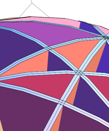
    $\begingroup$ I am experimenting with exporting Mathematica output in .stl format for 3d printing. This sort of exporting seems to work well if it only involves basic objects like cylinders but seems to prone to create problems when you try to export fancier stuff. Anyway, here is what a collection of cylinders looks like when you preview it at Shapeways. To determine that it's a 40-gon just output to pdf and then have a close look in a vector graphics program. $\endgroup$ Commented Jun 26, 2014 at 1:05
  • $\begingroup$ I pulled the version-8 tag since this applies multiple versions. $\endgroup$
    – Mr.Wizard
    Commented Jun 26, 2014 at 1:27
  • $\begingroup$ Be a bit careful with this, the printing engine may get confused by intersecting surfaces, as nothing physical can have these. It may leave the interior area open and your design would not work. Offcourse any mathematical preview would have no problem with intersection and it would be hard to see intersections. Altough shapeways is probably aware of this, but if you were to do this on your own then... $\endgroup$
    – joojaa
    Commented Jun 26, 2014 at 7:34

4 Answers 4

17
$\begingroup$

You can fix this problem by using the following Option in Graphics3D:

Method -> {"CylinderPoints" -> {200, 1}}

Adjust 200 to match your requirements. (Indeed the default is 40.)

Edit: I don't know exactly what the second parameter does, but using the single parameter form shown in the documentation linked below results in a big slow-down. I could guess that it is points in the other direction but that doesn't seem to make sense. Anyway I can't tell the visual difference between {200, 1} and {200, 200} but the former is much faster than the latter. ("CylinderPoints" -> 200 is apparently equivalent to "CylinderPoints" -> {200, 200}.)

You can make the change permanent with the Option Inspector by changing this value in the Graphics3DBoxOptions:

enter image description here

From Three-Dimensional Graphics Primitives:

Even though Cone, Cylinder, Sphere, and Tube produce high-quality renderings, their usage is scalable. A single image can contain thousands of these primitives. When rendering so many primitives, you can increase the efficiency of rendering by using special options to change the number of points used by default to render Cone, Cylinder, Sphere, and Tube. The "ConePoints" Method option to Graphics3D is used to reduce the rendering quality of each individual cone. Cylinder, sphere, and tube quality can be similarly adjusted using "CylinderPoints", "SpherePoints", and "TubePoints", respectively.

40 points:

enter image description here

200 points:

enter image description here

$\endgroup$
9
  • $\begingroup$ Crushed it as usual. What does the second element in the option setting do? I don't see an explanation in the docs. $\endgroup$
    – mfvonh
    Commented Jun 26, 2014 at 1:17
  • $\begingroup$ @mfvonh It is apparently superfluous based on the example in the tutorial I just linked. $\endgroup$
    – Mr.Wizard
    Commented Jun 26, 2014 at 1:24
  • $\begingroup$ Thank you very much for that. Exactly what I was looking for! $\endgroup$ Commented Jun 26, 2014 at 1:31
  • $\begingroup$ @Mr.Wizard I hope it was not presumptuous of me to add pictures to show your solution in all its glory :) $\endgroup$
    – mfvonh
    Commented Jun 26, 2014 at 1:33
  • $\begingroup$ @mfvonh Thanks for the examples! $\endgroup$
    – Mr.Wizard
    Commented Jun 26, 2014 at 1:33
9
$\begingroup$

The direct answer has been given by Mr. Wizard already, but there is also another way that renders smoothly while giving some additional advantages:

Use Tube instead of Cylinder. One advantage is that Tube allows you to do additional styling with VertexColors, not supported by Cylinder.

I will assume that we named your large list of Cylinder objects artwork. Using this, you can render the Tube version like this:

Graphics3D[{CapForm["Butt"], 
 artwork /. Cylinder -> Tube}, 
 Method -> {"TubePoints" -> 600}]

Tube

Here, TubePoints is the equivalent to CylinderPoints in Mr.Wizard's answer. I deliberately cranked up the number of points to 600 to see if there is any noticeable lag with Tube. It seems that this method produces output that is just as responsive as the Cylinder method with Method -> {"CylinderPoints" -> {600, 1}}.

Edit to address follow-up question about Export

As was not initially clear, the ultimate goal of the question is to produce a 3D graphics that can be exported to STL format at the same vertex count that is displayed in Mathematica.

This is not the case with solutions based on Cylinder or Tube as far as we've been able to tell so far. Therefore, I revisited another answer where I made a custom cylinder function motivated by the desire to incorporate VertexNormals. It's slight overkill here because that function allows an arbitrary cross-sectional shape which we don't need here. But since I already have it, this seemed easiest to me. Also, prism can be used in its own right to generalize the question.

First I recall the function prism from that answer, and then I wrap it by a function cyl that emulates a Cylinder between two points:

ClearAll[prism]
prism[pts_List, h_] := 
 Module[{bottoms, tops, surfacePoints, sidePoints},
  surfacePoints = 
   Table[Map[PadRight[#, 3, height] &, pts], {height, {0, h}}];
  {bottoms, tops} = {Most[#], Rest[#]} &@surfacePoints;
  sidePoints = 
   Flatten[{bottoms, RotateLeft[bottoms, {0, 1}], 
     RotateLeft[tops, {0, 1}], tops}, {{2, 3}, {1}}];
  MapThread[
   Polygon[#1, VertexNormals -> (#1 - #2)] &,
   {
    Join[sidePoints, surfacePoints],
    Join[Map[{0, 0, 1} # &, sidePoints, {2}],
     Map[({1, 1, 0} # + {0, 0, h/2}) &, surfacePoints, {2}]
     ]
    }
   ]
  ]

cyl[{pt1_, pt2_}, r_, n_: 90] := Module[{
   circle = 
    r Table[{Cos[ϕ], Sin[ϕ]}, {ϕ, Pi/n, 2 Pi, Pi/n}],
   h = EuclideanDistance[pt1, pt2]},
  GeometricTransformation[prism[circle, h], 
   Composition[TranslationTransform[pt1], 
    Quiet[Check[RotationTransform[{{0, 0, 1.}, pt2 - pt1}], 
      Identity]]]]]

gg = Graphics3D[artwork /. Cylinder -> cyl];

Export["gg.stl", gg]

The result is in gg, and the default vertex count around the perimeter is n=90. You can verify in an external program that this count is preserved in the Export. Here is what it looks like in Blender with the default 90 polygon points:

blender

$\endgroup$
4
  • $\begingroup$ Oops, looks like the second parameter was important after all! It's super slow without it. I'll be curious to know how this compares to Method -> {"CylinderPoints" -> {200, 1}} on your machine. $\endgroup$
    – Mr.Wizard
    Commented Jun 26, 2014 at 2:29
  • $\begingroup$ That does the trick! With Method -> {"CylinderPoints" -> {600, 1}} your plot seems to be just as responsive as the Tube version. So the speed isn't an issue anymore, and I'll edit my answer to account for your update. $\endgroup$
    – Jens
    Commented Jun 26, 2014 at 2:33
  • $\begingroup$ Good; I'm seeing the same behavior here. +1 for showing a different way. $\endgroup$
    – Mr.Wizard
    Commented Jun 26, 2014 at 2:34
  • $\begingroup$ Looks like a great solution with a lot of scope for refining the output, e.g. by using a ring as a cross-section instead of a circle to create an empty core. Thank you very much for your help with solving this problem, and thank you also again to Mr. Wizard. $\endgroup$ Commented Jun 26, 2014 at 4:52
6
$\begingroup$

Here's a replacement for Cylinder that uses splines.

Clear[splineCylinder];
splineCylinder[{a_, b_}, r_: 1] :=
  Module[{
    base = r {{0, -1, 0}, {1, -1, 0}, {1, 1, 0}, {0, 1, 0},
              {-1, 1, 0}, {-1, -1, 0}, {0, -1, 0}},
    weights = {1, 0.5, 0.5, 1, 0.5, 0.5, 1},
    knots = {0, 0, 0, 1/4, 1/2, 1/2, 3/4, 1, 1, 1},
    transform, baseA, baseB
    },
    transform = If[Chop@Cross[{0, 0, 1}, b - a] == {0, 0, 0}, Identity, 
      RotationTransform[{{0, 0, 1}, Normalize[b - a]}]];
    baseA = a + transform@# & /@ base;
    baseB = b + transform@# & /@ base;

    BSplineSurface[#, SplineDegree -> 2, SplineKnots -> {Automatic, knots}, 
      SplineWeights -> {weights, weights}, SplineClosed -> {False, True}] & /@
    {
      {baseA, baseB},
      {baseA, a + 0 # & /@ base},
      {baseB, b + 0 # & /@ base}
    }
  ]

It's smoother, yet slower. It also has a balloon knot in the centre of each cap. But you can't see that in your graphic.

splineCylinder

Edit: This fails utterly to be exported to an STL file. It appears that exporting a 3D spline is not yet fully implemented in Mathematica (9.0.1).

$\endgroup$
1
  • $\begingroup$ I was waiting for someone to post this. +1 $\endgroup$
    – Mr.Wizard
    Commented Jun 27, 2014 at 0:17
0
$\begingroup$

Perhaps you could hack together disks using a plotting function (and use PlotPoints if necessary)?

PolarPlot[1, {\[Theta], 0, 2 Pi}, PlotPoints -> 1000];
Cases[%, _Line, Infinity] /. {p__?NumberQ} :> {p, 0};
%[[1,1]] // Length
%% // Graphics3D

1761

enter image description here

$\endgroup$
1
  • $\begingroup$ I am experimenting with exporting Mathematica output in .stl format for 3d printing. This sort of exporting seems to work well if it only involves basic objects like cylinders but seems to prone to create problems when you try to export fancier stuff. Anyway, here is what a collection of cylinders looks like when you preview it at Shapeways. $\endgroup$ Commented Jun 26, 2014 at 1:00

Your Answer

By clicking “Post Your Answer”, you agree to our terms of service and acknowledge you have read our privacy policy.

Not the answer you're looking for? Browse other questions tagged or ask your own question.