30
$\begingroup$

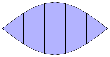
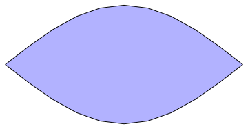
My question is strongly related to this question, nevertheless I would like to bring it to everyone's attention. Let's say I want to create a new graphics primitive Boing which should look like this

Boing[] := 
 Polygon[Join[#1, Reverse[#2]] & @@@ 
   Partition[
    Table[{2 x/Pi, y/2*Cos[x]}, {x, -Pi/2, Pi/2, 
      Pi/10}, {y, {-1, 1}}], 2, 1]]

Graphics[{Opacity[0.3, Blue], Boing[]}, 
 AspectRatio -> Automatic]

Mathematica graphics

As a new primitive, it should clearly work like other primitives like Disk, Rectangle, etc. When I define a FaceForm and EdgeForm one sees that this does not work because the settings are applied to the underlying Polygons

Graphics[{EdgeForm[Black], FaceForm[Opacity[0.3, Blue]], 
  Boing[]}, AspectRatio -> Automatic]

Mathematica graphics

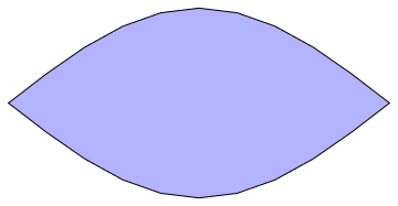
In this case one could slightly re-arrange the points and create one overall polygon to circumvent the issue

Boing[] := 
 Polygon[Join[#1, Reverse[#2]] & @@ 
   Transpose[
    Table[{2 x/Pi, y/2*Cos[x]}, {x, -Pi/2, Pi/2, 
      Pi/10}, {y, {-1, 1}}]]]
Graphics[{EdgeForm[Black], FaceForm[Opacity[0.3, Blue]], Boing[]}, 
 AspectRatio -> Automatic]

Mathematica graphics

Unless I am mistaken, this is in general not possible without having access to the current values of FaceForm and EdgeForm. Consider the following example where I don't see a direct way

Mathematica graphics

Question:

What is the simplest solution to create a new graphics primitive which works like e.g. a polygon? To clarify: I want to be able to manually construct a new primitive and define how the settings of the current graphics state like FaceForm or EdgeForm (Texture, Specularity or Lighting are further examples which change the state of the graphics engine) are handled.

Update:

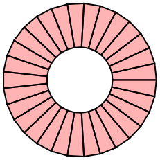
The answer of rm-rf was promising but unfortunately, Graphics`Mesh`PolygonCombine seems to have the same issues as I encountered above. This means, that for my target application it will not work. Consider the following example

points[r1_, r2_, n_] :=
  With[{dphi = 2.0 Pi/(n - 1)},
   Table[r {Cos[phi], Sin[phi]}, {phi, 0, 2 Pi, dphi}, {r, {r1, r2}}]
   ];

Graphics@{EdgeForm[{Black, Thick}], FaceForm[Opacity[0.3, Red]],
  Polygon[
   Function[{p1, p2}, Join[p1, Reverse[p2]]] @@@ 
    Partition[points[0.3, 0.7, 30], 2, 1]]}

Mathematica graphics

And with Graphics`Mesh`PolygonCombine we get

Mathematica graphics

$\endgroup$

5 Answers 5

21
$\begingroup$

I think you will need to use FilledCurve to create objects with holes in.

For example:

points[r1_, r2_, n_] := With[{dphi = 2.0 Pi/(n - 1)}, 
   Table[r {Cos[phi], Sin[phi]}, {phi, 0, 2 Pi, dphi}, {r, {r1, r2}}]];

poly = Polygon[Function[{p1, p2}, Join[p1, Reverse[p2]]] @@@ 
    Partition[points[0.3, 0.7, 30], 2, 1]];

prim = FilledCurve[Thread[Graphics`Mesh`PolygonCombine @ poly] /. 
    Polygon[data_] :> {Line[data]}];

To make something that behaves more like a graphics primitive I will use my answer from here

SetAttributes[createPrimitive, HoldAll];
createPrimitive[patt_, expr_] := 
 Typeset`MakeBoxes[p : patt, fmt_, Graphics] := 
  Typeset`MakeBoxes[Interpretation[expr, p], fmt, Graphics]

createPrimitive[donut, Evaluate@prim]

Now you can use donut in Graphics:

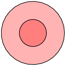
Graphics@{EdgeForm[{Black, Thick}], FaceForm[Opacity[0.3, Red]], donut}

enter image description here

Because donut has no downvalues, it remains unevaluated in the graphics expression:

InputForm[%]
(* Graphics[{EdgeForm[{GrayLevel[0], Thickness[Large]}], 
    FaceForm[Opacity[0.3, RGBColor[1, 0, 0]]], donut}] *)
$\endgroup$
2
  • $\begingroup$ I haven't considered FilledCurve because I was disappointed that there seems to be no way to access the current state of a Graphics in between the drawing steps. I was particularly interested in this because in OpenGL this is possible for textures, colors, etc. I know hacks around this, but I was really curious that no one seems to miss this. Your answer is nevertheless the most direct way in this case. +1 $\endgroup$
    – halirutan
    Commented Dec 13, 2013 at 16:14
  • $\begingroup$ @halirutan Not being able to access it might turn out to be a more serious problem when trying to write an exporter to another format which doesn't directly map to Mma's graphics representation. $\endgroup$
    – Szabolcs
    Commented Dec 13, 2013 at 20:31
16
$\begingroup$

You can use the undocumented PolygonCombine to create a single polygon which behaves well with EdgeForm and FaceForm:

Boing2[] := Graphics`Mesh`PolygonCombine@Boing[]
Graphics[{EdgeForm[Black], FaceForm[Opacity[0.3, Blue]], Boing2[]}, AspectRatio -> Automatic]

In Mathematica 10/Wolfram Language/Mathematica-RPi, the function can be found under Graphics`PolygonUtils`. There might be some issues with self-intersecting polygons (I haven't looked into it), but this is a good start.

$\endgroup$
2
  • $\begingroup$ It is indeed a good start. Thanks for this answer! $\endgroup$
    – halirutan
    Commented Dec 13, 2013 at 1:55
  • 5
    $\begingroup$ Unfortunately, for things with holes it doesn't work. $\endgroup$
    – halirutan
    Commented Dec 13, 2013 at 2:26
5
$\begingroup$

In Mathematica 12 BoundaryMeshRegion objects can be used as a Graphics primitive. So, another idea is to use a BoundaryMeshRegion as your primitive. For example:

Typeset`MakeBoxes[
    CutoutEllipse[center_, out_, in_],
    form_,
    Graphics
] := With[
    {
    new = Replace[
        RegionDifference[Disk[center, out], Disk[center, in]],
        b_BooleanRegion :> BoundaryDiscretizeRegion[b]
    ]
    },
    Typeset`MakeBoxes[new, form, Graphics]
]

Examples:

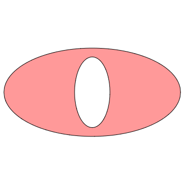
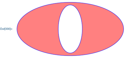
Graphics[{Pink, EdgeForm[Blue], CutoutEllipse[{0,0}, {4,2}, .9 {1,2}]}]

enter image description here

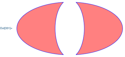
Graphics[{Pink, EdgeForm[Blue], CutoutEllipse[{0,0}, {4,2}, 1.1 {1,2}]}]

enter image description here

You can use this answer to get the above approach to work in earlier versions of Mathematica.

$\endgroup$
1
  • $\begingroup$ In V12 we can also have explicitly have polygons with holes. $\endgroup$
    – Greg Hurst
    Commented May 24, 2019 at 16:12
4
$\begingroup$

FilledCurve seems to do exactly what you want

$\endgroup$
3
  • $\begingroup$ Do you mind including in your answer how to plot the examples given in the question by using FilledCurve? $\endgroup$ Commented Dec 13, 2013 at 9:00
  • 3
    $\begingroup$ Sorry , didn't included it because the example in the first page of the reference documentation is really close to the requirement. Just needs a few adjustments for the shape. $\endgroup$ Commented Dec 13, 2013 at 10:31
  • $\begingroup$ Don't bother now. @SimonWoods did it. $\endgroup$ Commented Dec 13, 2013 at 17:08
2
$\begingroup$

Posting a separate answer, as this is really a completely different approach. While it seems impossible to access the current setting for FaceForm and EdgeForm in between the drawing steps, it is possible to temporarily change them for a particular primitive with Style.

So you can show the original polygon with no edges, and the combined polygon with no faces:

points[r1_, r2_, n_] := With[{dphi = 2.0 Pi/(n - 1)}, 
   Table[r {Cos[phi], Sin[phi]}, {phi, 0, 2 Pi, dphi}, {r, {r1, r2}}]];

poly = Polygon[Function[{p1, p2}, Join[p1, Reverse[p2]]] @@@ 
    Partition[points[0.3, 0.7, 30], 2, 1]];

Graphics[{EdgeForm[{Black, Thick}], FaceForm[Opacity[0.3, Red]], 
  Style[poly, EdgeForm[]], 
  Style[Graphics`Mesh`PolygonCombine[poly], FaceForm[]]
  }]

enter image description here

$\endgroup$

Your Answer

By clicking “Post Your Answer”, you agree to our terms of service and acknowledge you have read our privacy policy.

Not the answer you're looking for? Browse other questions tagged or ask your own question.