12
$\begingroup$

Consider this toy example:

$$\newcommand{\p}{\partial}\newcommand{\f}{\frac} \left\{\begin{array}{l}\f{\p^2 u}{\p x \p y}=1\\ \left.u\right|_{x=0}=0\\ \left.u\right|_{y=0}=0\end{array}\right.$$

Obviously, the solution is $u=xy$, and the old good MethodOfLines can handle the problem well:

sys = With[{u = u[x, y]}, 
           {D[u, x, y] == 1, u == 0 /. x -> 0, u == 0 /. y -> 0}]

solref = NDSolveValue[sys, u, {x, 0, 1}, {y, 0, 1}];

Plot3D[solref[x, y], {x, 0, 1}, {y, 0, 1}]

enter image description here

Remark

"How do you know MethodOfLines is used in this case?" This is discussed in the following post:

PDEs : automatic method choice : TensorProductGrid or FiniteElement?

But if we force NDSolve to use FiniteElement method, the result will be terrible:

solfem = NDSolveValue[sys, u, {x, 0, 1}, {y, 0, 1}, Method -> "FiniteElement"];

Plot3D[solfem[x, y], {x, 0, 1}, {y, 0, 1}]

enter image description here

Why does FiniteElement method give a rather inaccurate (if we don't call it incorrect) solution? Is it a limitation of finite element method (FEM)? If so, can you elaborate? If not, how can we adjust FiniteElement method of NDSolve to make it produce an acceptable solution?

Please notice this question focuses on FEM, so solutions for the toy example via other methods are not of interest.

$\endgroup$
10
  • $\begingroup$ Nice question! How do you come to the conclusion "MethodOfLines is used"? Your link only checks for "FiniteElementMethod" I think. $\endgroup$ Commented Dec 2 at 11:09
  • $\begingroup$ @UlrichNeumann Because all the condition for triggering FEM isn't inside this NDSolve :) . And a critical evidence is, solref["ElementMesh"] returns None; another critical evidence is: i.sstatic.net/lEHjwX9F.png For comparison, the solution returned by FEM is: i.sstatic.net/nSb0NvhP.png $\endgroup$
    – xzczd
    Commented Dec 2 at 11:26
  • $\begingroup$ That is clear to me, but your implication "Not[FiniteElement] => MethodOfLines" isn't correct I think. $\endgroup$ Commented Dec 2 at 11:30
  • $\begingroup$ @UlrichNeumann This is correct, because currently (v14.1) MethodOfLines and FiniteElement are the only two methods available in NDSolve for PDE solving. $\endgroup$
    – xzczd
    Commented Dec 2 at 11:33
  • 2
    $\begingroup$ @UlrichNeumann Perhaps not a mathematical proof: solmol = NDSolveValue[sys, u, {x, 0, 1}, {y, 0, 1}, Method -> "MethodOfLines"]; solmol === solref evaluates to True. It's unlikely distinct numerical methods produce identical solutions. In any case, an explicit MOL produces the same result. $\endgroup$
    – Michael E2
    Commented Dec 2 at 11:59

2 Answers 2

10
$\begingroup$

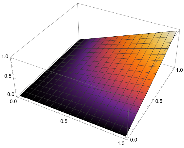
The problem is that there are no boundary conditions at $x=1, y=1$. As we know, in this case Mathematica FEM has an automatic option to apply zero Neumann value. Since these boundary conditions are not consistent with solution we have unstably result shown above. To avoid these discrepancies, we can apply Dirichlet conditions at $x=1, y=1$ as follows (we use low-level FEM-programming)

Needs["NDSolve`FEM`"]
bmesh = ToBoundaryMesh[
   "Coordinates" -> {{0., 0.}, {1, 0.}, {1, 1}, {0., 1}, {0.5, 0.5}}, 
   "BoundaryElements" -> {LineElement[{{1, 2}, {2, 3}, {3, 4}, {4, 
        1}}]}];
mesh = ToElementMesh[bmesh, "MaxCellMeasure" -> 0.01]
vd = NDSolve`VariableData[{"DependentVariables", 
     "Space"} -> {{u}, {x, y}}];
sd = NDSolve`SolutionData[{"Space"} -> {mesh}];
cdata = InitializePDECoefficients[vd, sd, 
   "DiffusionCoefficients" -> {{{{0, 1/2}, {1/2, 0}}}}, 
   "LoadCoefficients" -> {{1}}];
bcdata = 
  InitializeBoundaryConditions[vd, 
   sd, {{DirichletCondition[u[x, y] == 0, x == 0], 
     DirichletCondition[u[x, y] == 0, y == 0], 
     DirichletCondition[u[x, y] == y, x == 1], 
     DirichletCondition[u[x, y] == x, y == 1]}}];
mdata = InitializePDEMethodData[vd, sd];
dpde = DiscretizePDE[cdata, mdata, sd];
dbc = DiscretizeBoundaryConditions[bcdata, mdata, sd];
{load, stiffness, damping, mass} = dpde["All"];
DeployBoundaryConditions[{load, stiffness}, dbc];

v = LinearSolve[stiffness, load, 
    Method -> "Pardiso"][[1 ;; Length[mass]]];

solfun = ElementMeshInterpolation[{mesh}, v];

Plot3D[solfun[x, y], {x, y} \[Element] mesh, 
 ColorFunction -> "SunsetColors"]

Figure 1

$\endgroup$
11
  • $\begingroup$ Interesting. Further tests show that this behavior seems to be related to the Div term in formal PDE of FEM: NDSolveValue[{u'[x] == 1, u[0] == 0}, u, {x, 0, 1}, Method -> "FiniteElement"] gives the desired solution, but NDSolve[{-1 + Inactive[Div][{1} u[x], {x}] == 0, u[0] == 0}, u, {x, 0, 1}] doesn't. (In former case, the u'[x] has been transformed to part of the convection (Inactive[Grad][…]) term. ) $\endgroup$
    – xzczd
    Commented Dec 3 at 7:16
  • $\begingroup$ @AlexTrounev Interesting workaround. I also tried to avoid this automatism "zero Neumann value" in my answer, but result isn't smooth. No idea why. $\endgroup$ Commented Dec 3 at 8:10
  • $\begingroup$ It's also interesting that, low-level FEM seems to be necessary and something like NDSolveValue[{sys[[1]], DirichletCondition[u[x, y] == x y, True]}, u, {x, 0, 1}, {y, 0, 1}] won't result in the desired solution. (Parser defect?) $\endgroup$
    – xzczd
    Commented Dec 3 at 8:26
  • $\begingroup$ @xzczd The main idea of my solution is not to give NDSolve any possibilities to apply automatic option to the x=1, y=1. As we can see from all observed examples this option hidden very deep in the Mathematica FEM :) $\endgroup$ Commented Dec 3 at 10:26
  • $\begingroup$ @UlrichNeumann In your example you are not using InitializeBoundaryConditions, DiscretizeBoundaryConditions, and DeployBoundaryConditions to avoid automatic option with zero NeumannValue ; ) Obviously this option is hidden in DiscretizePDE. $\endgroup$ Commented Dec 3 at 10:39
6
$\begingroup$

final modification

Strange!

If we use Mathematicas FEM capabilities step by step, introducing DirichletConditions at the end, we get better results:

Needs["NDSolve`FEM`"]

mesh

mesh = ToElementMesh[Rectangle[],"MeshElementType" -> "TriangleElement","MeshOrder" -> 1]
mreg = MeshRegion[mesh];
pts = MeshCoordinates[mreg];

boundary DirichletCondition

rand = MeshCells[MeshRegion[mesh], {0, "Boundary"}][[All, 1]];
randD = Select[rand, (pts[[# ]][[1]] == 0 || pts[[# ]][[2]] == 0 &)]
rand1 = MeshCells[MeshRegion[mesh], {1, "Boundary"}][[All, 1]];

discretization(Mathematica buildin)

nr = ToNumericalRegion[mesh];
vd = NDSolve`VariableData[{"DependentVariables" -> {u},"Space" -> {x, y}}];
sd = NDSolve`SolutionData[{"Space" -> nr}];

coefficients = {"DiffusionCoefficients" -> {{-{{0, -1/2}, { -1/2,0}}}}, "LoadCoefficients" -> {{1}}}; 
initCoeffs =InitializePDECoefficients[vd, sd, coefficients];
methodData = InitializePDEMethodData[vd, sd];
discretePDE = DiscretizePDE[initCoeffs, methodData, sd];
M11 = discretePDE["StiffnessMatrix"] // Normal;
rS = Flatten[discretePDE["LoadVector"] // Normal, 1];

solution M11.p-rS==0 && dirichlet==0

p = Table[u[i], {i, Length[pts]}]; (* unkowns*)
dirichlet = Table[p[[i]] == 0, {i, randD}]; (* DirchletCondition*)

mini = NMinimize[{# . # &[M11 . p - rS], dirichlet}, p]; 
Plot3D[Evaluate@ElementMeshInterpolation[mesh, Values[mini[[2]]]][x, y],Element[{x, y}, mreg]] 
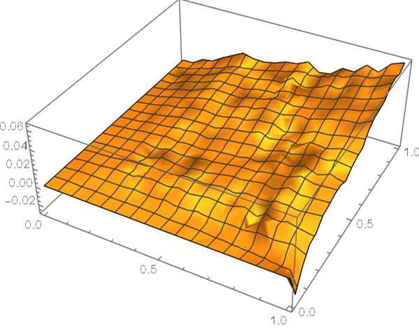
enter image description here

Result approximates expected function u[x,y]==x y much better than "terrible" NDSolve result.

final addendum

Thanks @AlexTrounev for his helpful comment

discretePDE["StiffnessMatrix"] only evaluates the first part of Green's identity, assuming second part(line integral) equal zero(NeumannValue==0)

To get the correct discretization we have to add second part of Green's identity enter image description here

I don't know if discretePDE provides this integral somewhere, that's why I choose a selfmade numerical approach

line integration(Gaussian)

linienintegralGaussNeumann[rand_, funx_, funy_, 
  pi_] := (*rand besteht aus Indexpaaren des Randes *)
 Block[{w0 = 8/18, w1 = 5/18, gt = 1/2, 
   gdt = Sqrt[3/5]/2,(*Gausspunkte tt-dtt,tt,tt+dtt*)
   x0, y0, x1, y1, x2, y2, p1, p2, nx, ny},
  Total@Map[( 
       {p1, p2} = pi[[# ]];(*Punkte Randelement*)
       {nx, ny} = #/Sqrt[# . #] &[Cross[p2 - p1]];(* 
       Normalenvektor *)
       
        (* 3Gausspunkte*)
       {x0, y0} = (1 - gt) p1 + gt p2;
       {x1, y1} = (1 - (gt - gdt )) p1 + (gt - gdt ) p2;
       {x2, y2} = (1 - (gt + gdt)) p1 + (gt + gdt) p2;
       1/2 Norm[p2 - p1](* 
        Sehnenlänge*)(nx (funx[x1, y1] w1 + funx[x0, y0] w0 + 
             funx[x2, y2] w1) + 
          ny (funy[x1, y1] w1 + funy[x0, y0] w0 + 
             funy[x2, y2] w1) )) &, rand ](*//Rationalize[#,0]&*)/. 
   0. -> 0
  ]

boundary

\[Phi]i =Map[ElementMeshInterpolation[mesh, #] &,IdentityMatrix[Length[pts]]] ;   
\[Phi] = Map[ # [x, y] &, \[Phi]i] ;
\[Phi]x = Map[Derivative[1, 0][#][x, y] &, \[Phi]i] ;
\[Phi]y = Map[Derivative[0, 1][#][x, y] &, \[Phi]i] ;


intGreen = 
linienintegralGaussNeumann[rand1 , 
Function[{x, y}, Outer[Times, \[Phi] , \[Phi]y] // Evaluate], 
Function[{x, y}, Outer[Times, \[Phi] , \[Phi]x] // Evaluate], pts];

p = Table[u[i], {i, Length[pts]}];
dirichlet = Table[p[[i]] == 0, {i, randD}];
mini = NMinimize[{# . # &[ ((M11 - intGreen) . p - rS) ],dirichlet},
p]; 
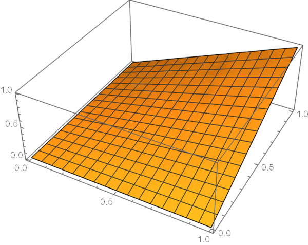
Plot3D[Evaluate@ElementMeshInterpolation[mesh, Values[mini[[2]]]][x, y], Element[{x, y}, mesh]]

Plot shows correct result of modified FEM (Galerkin method)!
enter image description here

Hope it helps!

$\endgroup$
15
  • $\begingroup$ Ah this is relatively easy to explain. Yours is different from the default FEM because: 1. The mesh is different. 2. NMinimize rather than LinearSolve is used to solve the system. If we: 1. Use the same mesh in NDSolve. 2. Use e.g. rSnew = Module[{r = rS}, r[[randD]]=0.; r];M11new=Module[{m = M11,c=ConstantArray[0., Length@rS]}, (m[[#]] = ReplacePart[c,#->1]) &/@randD; m]; mini2 = LinearSolve[M11new, rSnew]; Plot3D[Evaluate@ElementMeshInterpolation[mesh, mini2][x, y],{x, y}∈mreg] the solution will be almost the same. Also, this solution is just smoother, but still far beyond correct… $\endgroup$
    – xzczd
    Commented Dec 2 at 12:13
  • $\begingroup$ Forget to mention: "DiffusionCoefficients" should be {{{{0, 1/2}, {1/2, 0}}}}. $\endgroup$
    – xzczd
    Commented Dec 2 at 12:18
  • $\begingroup$ Last modification concerning discretePDE is absolutely right (+1}. The question is how discretePDE working with method of lines? Inside discretePDE we see branches dependent on method. $\endgroup$ Commented Dec 4 at 10:21
  • $\begingroup$ @AlexTrounev How did you look inside DiscretizePDE? $\endgroup$ Commented Dec 4 at 16:55
  • $\begingroup$ @UlrichNeumann Use GeneralUtilities`PrintDefinitions@DiscretizePDE $\endgroup$ Commented Dec 4 at 19:20

Your Answer

By clicking “Post Your Answer”, you agree to our terms of service and acknowledge you have read our privacy policy.

Not the answer you're looking for? Browse other questions tagged or ask your own question.