4
$\begingroup$

I observed a strange behavior using Polygon with Graphics3D in MMA14.1.

Here is my example.

    polygon = {{-0.4, 1.7, 0.}, {-0.8, 1.7, 0.}, {-1.2, 1.8, 0.}, {-1.4, 
    1.9, 0.}, {-1.5, 2., 0.}, {-1.5, -0.5, 0.}, {1, -0.5, 0.}, {1, 
    1.8, 0.}};
    hole = {{0., 0., 0}, {0.5, 0., 0.}, {0.5, 0.5, 0.}, {0., 0.5, 0.}};
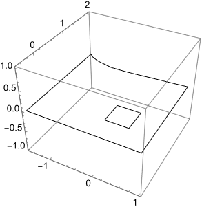
    Graphics3D[Polygon[polygon -> hole], Axes -> True]

Its result is an unfilled 3D polygon on the XY-plane.

enter image description here

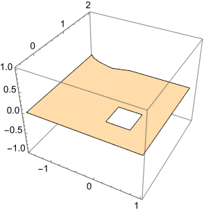
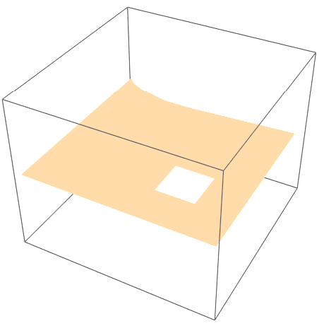
However, by slightly changing the first coordinate, for example ( {-0.4, 1.7, 0.} -> {-0.4, 1.8, 0.} ), it works as expected.

enter image description here

Could someone please explain this situation?

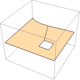
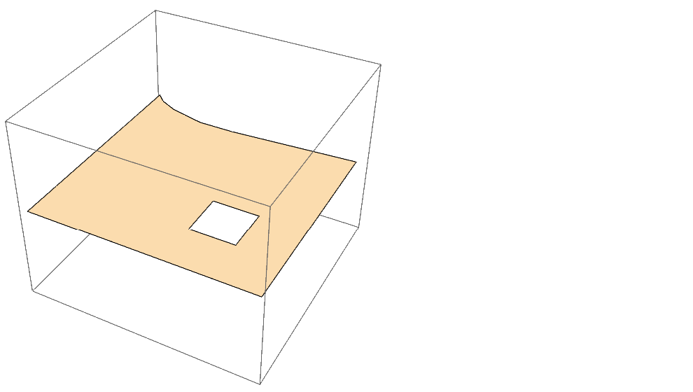
According to the suggestion from user64494

Graphics3D[
 Polygon[Join @@ (Append[#, #[[1]]] & /@ {polygon, Reverse[hole]})]]

enter image description here

$\endgroup$
1
  • $\begingroup$ As Wiki says "Polygons with holes can be dissected into multiple polygons by adding new edges, so they are not frequently needed". $\endgroup$
    – user64494
    Commented Sep 14 at 7:14

2 Answers 2

3
$\begingroup$

Edit

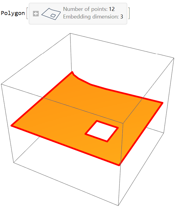
For version 14.1.0, we can use DiscreteRegioin+RegionPlot3D ( but version 14.0.0 does not work)

(* Version 14.1.0  *)
poly = Polygon[polygon -> hole]
RegionPlot3D[DiscretizeRegion@poly, 
 BoundaryStyle -> Directive@{Red, Thickness[.01]}]

enter image description here

Original

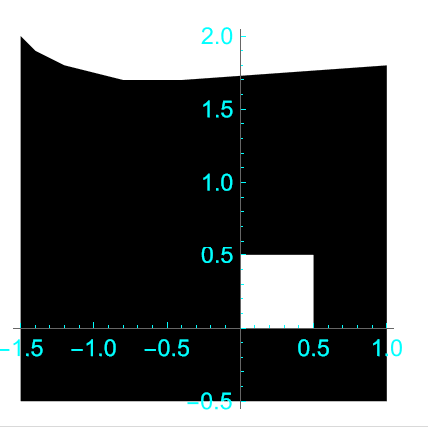
The 2D case work , it seems be a bug.

reg2d = Polygon[polygon[[;; , {1, 2}]] -> hole[[;; , {1, 2}]]];
(* reg2d = BoundaryMeshRegion[
  Join[polygon[[;; , {1, 2}]], 
   hole[[;; , {1, 2}]]], {Line[{1, 2, 3, 4, 5, 6, 7, 8, 1}], 
   Line[{9, 10, 11, 12, 9}]}] *)
Graphics[reg2d, Axes -> True, TicksStyle -> Cyan]

enter image description here

reg3d = RegionProduct[reg2d, Point[{0.}]];
Graphics3D[{EdgeForm[], reg3d}]

enter image description here

$\endgroup$
2
  • 1
    $\begingroup$ Oh, is that so? Could you please report this to Wolfram? $\endgroup$
    – qwerty
    Commented Sep 14 at 6:56
  • $\begingroup$ Please see this question here $\endgroup$
    – Laurenso
    Commented Sep 15 at 9:22
2
$\begingroup$

The behaviour is explained in the documentation for RenderingOptions:

Nearly coplanar polygons may be rendered inconsistently by default rendering methods.

You can change the rendering method to get the correct result:

polygon = {{-0.4, 1.7, 0.}, {-0.8, 1.7, 0.}, {-1.2, 1.8, 0.}, {-1.4, 1.9, 0.}, 
           {-1.5, 2., 0.}, {-1.5, -0.5, 0.}, {1, -0.5, 0.}, {1, 1.8, 0.}};
hole = {{0., 0., 0}, {0.5, 0., 0.}, {0.5, 0.5, 0.}, {0., 0.5, 0.}};
p1 = Polygon[polygon -> hole]

Style[Graphics3D[p1], RenderingOptions -> {"3DRenderingMethod" -> "BSPTree"}]

enter image description here

$\endgroup$
4
  • 2
    $\begingroup$ OP points are NOT "nearly coplanar". They are coplanar exactly. You can replace the coordinates with exact values by applying Rationalize and the bug still persist. $\endgroup$ Commented Sep 14 at 10:16
  • $\begingroup$ @azerbajdzan, generally, there is no such thing as exact when doing numerical computations. There are various types of numerical errors, which can lead to wrong results. Obviously, I don't have a proof that this is the real reason here, just my hunch. Note that Rationalize has absolutely no effect here, because rendering is not done with exact arithmetics. $\endgroup$
    – Domen
    Commented Sep 14 at 12:00
  • $\begingroup$ The point is that the error is not on the user's side as the user provided input in the most accurate form. The error is on the side of the software. Anyway your answer is useful as a workaround. $\endgroup$ Commented Sep 14 at 12:10
  • $\begingroup$ I thank you both for very thought-provoking discussions. $\endgroup$
    – qwerty
    Commented Sep 14 at 12:28

Your Answer

By clicking “Post Your Answer”, you agree to our terms of service and acknowledge you have read our privacy policy.

Not the answer you're looking for? Browse other questions tagged or ask your own question.