4
$\begingroup$

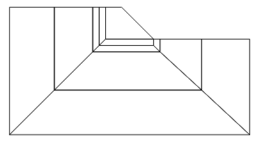
I have created the following mesh for a slope stability problem:

<< NDSolve`FEM`
    coordinates = {{0., 0.}, {75, 0}, {75, 30}, {45, 30}, {35, 40}, {0, 
        40}, {14, 14}, {60, 14}, {26, 26}, {47, 26}, {28, 28}, {45, 
        28}, {30, 30}, {47, 30}, {60, 30}, {14, 40}, {26, 40}, {28, 
        40}, {30, 40}};
    e1 = QuadElement[{{1, 2, 8, 7}, {2, 3, 15, 8}, {7, 8, 10, 9}, {8, 15, 
         14, 10}, {10, 14, 4, 12}, {9, 10, 12, 11}, {11, 12, 4, 13}, {13, 
         4, 5, 19}, {11, 13, 19, 18}, {9, 11, 18, 17}, {7, 9, 17, 16}, {1,
          7, 16, 6}}];
    mesh = ToElementMesh["Coordinates" -> coordinates, 
      "MeshElements" -> {e1}, "MeshOrder" -> 2, MaxCellMeasure -> 1]
    mesh["Wireframe"]

enter image description here

I'm specifing that the MaxCellMeasure shouldn't be larger than one, but mma refuses to refine the mesh. Is there a way to refine this mesh?

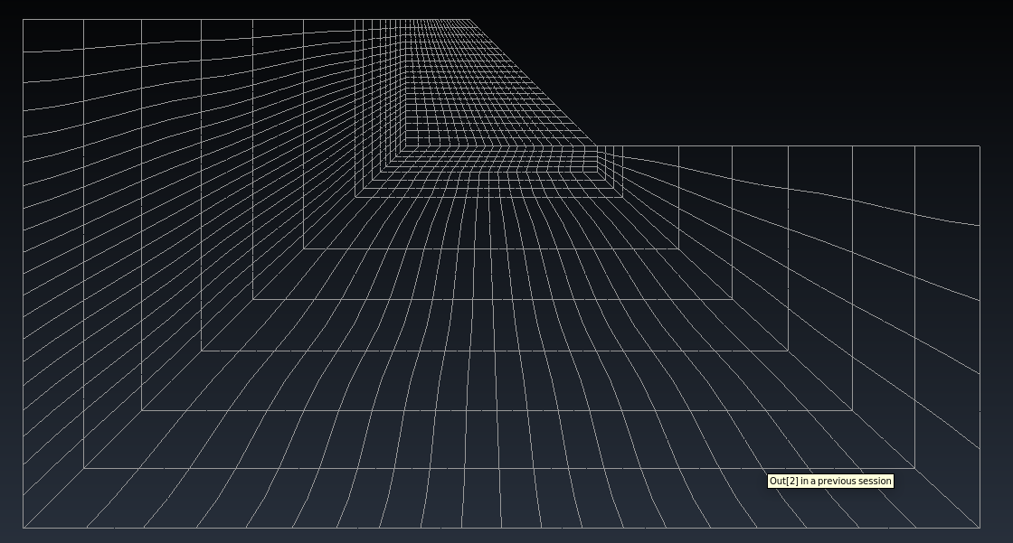
This is what I need (mesh generated by GID):

enter image description here

I have also tried to create a Region:

<< NDSolve`FEM`
top = {{1, 2, 8, 7}, {2, 3, 15, 8}, {7, 8, 10, 9}, {8, 15, 14, 
    10}, {10, 14, 4, 12}, {9, 10, 12, 11}, {11, 12, 4, 13}, {13, 4, 5,
     19}, {11, 13, 19, 18}, {9, 11, 18, 17}, {7, 9, 17, 16}, {1, 7, 
    16, 6}};
node = {{0., 0.}, {75, 0}, {75, 30}, {45, 30}, {35, 40}, {0, 40}, {14,
     14}, {60, 14}, {26, 26}, {47, 26}, {28, 28}, {45, 28}, {30, 
    30}, {47, 30}, {60, 30}, {14, 40}, {26, 40}, {28, 40}, {30, 40}};
reg = RegionUnion[
  Flatten[Table[
    Polygon[Table[{ node[[ top[[i]][[j]] ]][[1]], 
       node[[ top[[i]][[j]] ]][[2]] }, {j, 1, 4}]], {i, 1, 
     Length[top]}]]]
Region[reg]
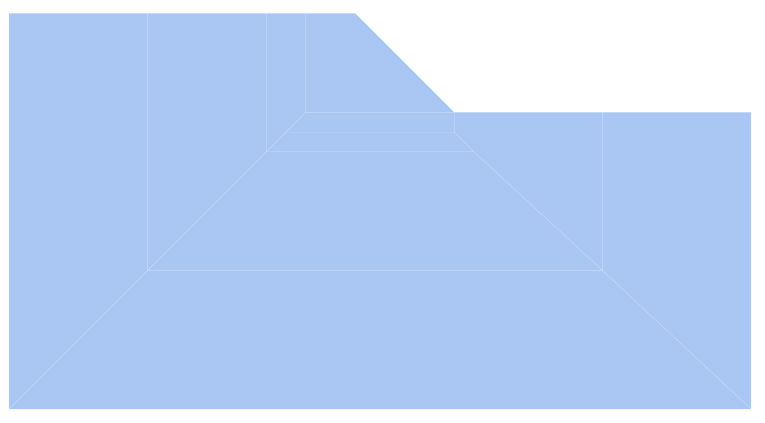
enter image description here But the function ToElementMesh doesn't work:

me = ToElementMesh[reg]
me["Wireframe"]
$\endgroup$
10
  • $\begingroup$ Try DiscretizeRegion[Region[reg], MaxCellMeasure -> 1] $\endgroup$ Commented Feb 7, 2022 at 14:37
  • $\begingroup$ This will return a triangular element mesh. I need quadrilaterals... $\endgroup$
    – Stratus
    Commented Feb 7, 2022 at 14:39
  • $\begingroup$ @Diogo, when you get this to work, would you be able to share the simulation? I'd be interested to se how it's done. $\endgroup$
    – user21
    Commented Feb 7, 2022 at 20:07
  • $\begingroup$ @user21 I have shared one of my results. Thank you for your interest. $\endgroup$
    – Stratus
    Commented Feb 7, 2022 at 21:04
  • $\begingroup$ @Diogo, thank you - did you implement the Mohr-Coulomb model in Mathematica? $\endgroup$
    – user21
    Commented Feb 8, 2022 at 5:41

2 Answers 2

4
$\begingroup$

There is no direct way to do it.But with a bit of programming it's not impossible. We (install and) load the FEMAddOns:

(*ResourceFunction["FEMAddOnsInstall"][]*)
Needs["FEMAddOns`"]

This has the function StructuredMesh.

coordinates = {{0., 0.}, {75, 0}, {75, 30}, {45, 30}, {35, 40}, {0, 
    40}, {14, 14}, {60, 14}, {26, 26}, {47, 26}, {28, 28}, {45, 
    28}, {30, 30}, {47, 30}, {60, 30}, {14, 40}, {26, 40}, {28, 
    40}, {30, 40}};
incidents = {{1, 2, 8, 7}, {2, 3, 15, 8}, {7, 8, 10, 9}, {8, 15, 14, 
    10}, {10, 14, 4, 12}, {9, 10, 12, 11}, {11, 12, 4, 13}, {13, 4, 5,
     19}, {11, 13, 19, 18}, {9, 11, 18, 17}, {7, 9, 17, 16}, {1, 7, 
    16, 6}};

mesh = ToElementMesh["Coordinates" -> coordinates, 
   "MeshElements" -> {QuadElement[incidents]}, "MeshOrder" -> 2, 
   MaxCellMeasure -> 1];
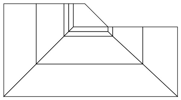
mesh["Wireframe"]

enter image description here

We use this to scroll through the structure:

Manipulate[
 Show[mesh["Wireframe"], 
  Graphics[Polygon[coordinates[[incidents[[n]]]]]]], {n, 1, 
  Length[incidents], 1}]

For one component

coordinates[[incidents[[8]]]]

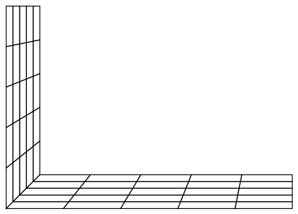
(*{{30, 30}, {45, 30}, {35, 40}, {30, 40}}*)

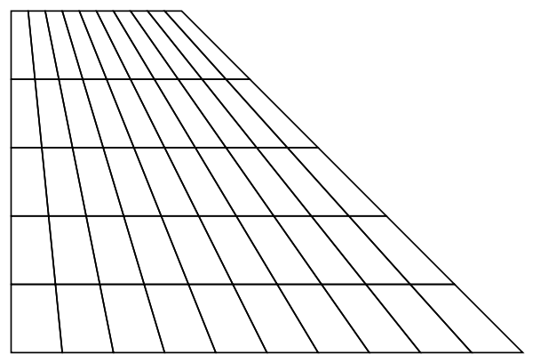
We use

raster = {{{30, 30}, {45, 30}}, {{30, 40}, {35, 40}}};
tempMesh1 = StructuredMesh[raster, {10, 5}];
tempMesh1["Wireframe"]

enter image description here

For the next component we use

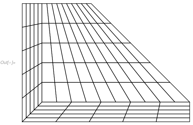
coordinates[[incidents[[#]]]] & /@ {7, 9}
(*{{{28, 28}, {45, 28}, {45, 30}, {30, 30}}, {{28, 28}, {30, 30}, {30, 
   40}, {28, 40}}}*)

raster = {{{45, 28}, {45, 30}}, {{28, 28}, {30, 30}}, {{28, 40}, {30, 
     40}}};
tempMesh2 = StructuredMesh[raster, {5, 10}];
tempMesh2["Wireframe"]

enter image description here

Next, we merge these to meshes. This only works if the nodes of the edges are at exactly the same positions.

ElementMeshJoin[m1_, m2_] := Module[
  {c1, c2, nc1, newEle, markers, eleTypes},
  c1 = m1["Coordinates"];
  c2 = m2["Coordinates"];
  nc1 = Length[c1];
  
  newEle = m2["MeshElements"];
  eleTypes = Head /@ newEle; 
  If[ElementMarkersQ[newEle], markers = ElementMarkers[newEle],
   markers = Sequence[]
   ]; newEle = 
   MapThread[#1[##2] &, {eleTypes, ElementIncidents[newEle] + nc1, 
     markers}];
  
  emesh = 
   ToElementMesh["Coordinates" -> Join[c1, c2], 
    "MeshElements" -> Flatten[{m1["MeshElements"], newEle}]];
  
  emesh
  ]

Join the meshes:

newMesh = ElementMeshJoin[tempMesh1, tempMesh2];
newMesh["Wireframe"]

enter image description here

Note carefully that the above mesh has hanging nodes but you get the idea.

The idea is then to do this for the remaining parts.

To then get a second order mesh, use

finalMesh = MeshOrderAlteration[newMesh, 2];

Other alternatives for quad dominant meshes can be found here

$\endgroup$
3
  • $\begingroup$ Thank you. This works for me! $\endgroup$
    – Stratus
    Commented Feb 7, 2022 at 17:20
  • $\begingroup$ Is it possible to set to 8 instead of 4 noded elements? $\endgroup$
    – Stratus
    Commented Feb 7, 2022 at 17:35
  • 1
    $\begingroup$ @Diogo, use MeshOrderAlteration; see update. $\endgroup$
    – user21
    Commented Feb 7, 2022 at 17:52
3
$\begingroup$
Needs["MeshTools`"]
    ElementMeshJoin[m1_, m2_] := 
     Module[{c1, c2, nc1, newEle, markers, eleTypes}, 
      c1 = m1["Coordinates"];
      c2 = m2["Coordinates"];
      nc1 = Length[c1];
      newEle = m2["MeshElements"];
      eleTypes = Head /@ newEle;
      If[ElementMarkersQ[newEle], markers = ElementMarkers[newEle], 
       markers = Sequence[]]; 
      newEle = MapThread[#1[##2] &, {eleTypes, 
         ElementIncidents[newEle] + nc1, markers}];
      emesh = 
       ToElementMesh["Coordinates" -> Join[c1, c2], 
        "MeshElements" -> Flatten[{m1["MeshElements"], newEle}]];
      emesh]
    c = {{0., 0.}, {75, 0}, {75, 30}, {45, 30}, {35, 40}, {0, 40}, {14, 
        14}, {60, 14}, {26, 26}, {47, 26}, {28, 28}, {45, 28}, {30, 
        30}, {47, 30}, {60, 30}, {14, 40}, {26, 40}, {28, 40}, {30, 40}};
    t = {{1, 2, 8, 7}, {2, 3, 15, 8}, {7, 8, 10, 9}, {8, 15, 14, 10}, {10,
         14, 4, 12}, {9, 10, 12, 11}, {11, 12, 4, 13}, {13, 4, 5, 
        19}, {11, 13, 19, 18}, {9, 11, 18, 17}, {7, 9, 17, 16}, {1, 7, 16,
         6}};
    raster = {{c[[2]], c[[8]]}, {c[[1]], c[[7]]}};
    tempMesh1 = StructuredMesh[raster, {10, 10}];
    
    raster = {{c[[3]], c[[15]]}, {c[[2]], c[[8]]}};
    tempMesh2 = StructuredMesh[raster, {10, 10}];
    
    raster = {{c[[8]], c[[10]]}, {c[[7]], c[[9]]}};
    tempMesh3 = StructuredMesh[raster, {10, 10}];
    
    raster = {{c[[15]], c[[14]]}, {c[[8]], c[[10]]}};
    tempMesh4 = StructuredMesh[raster, {10, 10}];
    
    raster = {{c[[14]], c[[4]]}, {c[[10]], c[[12]]}};
    tempMesh5 = StructuredMesh[raster, {10, 10}];
    
    raster = {{c[[10]], c[[12]]}, {c[[9]], c[[11]]}};
    tempMesh6 = StructuredMesh[raster, {10, 10}];
    
    raster = {{c[[12]], c[[4]]}, {c[[11]], c[[13]]}};
    tempMesh7 = StructuredMesh[raster, {10, 10}];
    
    raster = {{c[[4]], c[[5]]}, {c[[13]], c[[19]]}};
    tempMesh8 = StructuredMesh[raster, {10, 10}];
    
    raster = {{c[[11]], c[[13]]}, {c[[18]], c[[19]]}};
    tempMesh9 = StructuredMesh[raster, {10, 10}];
    
    raster = {{c[[9]], c[[11]]}, {c[[17]], c[[18]]}};
    tempMesh10 = StructuredMesh[raster, {10, 10}];
    
    raster = {{c[[7]], c[[9]]}, {c[[16]], c[[17]]}};
    tempMesh11 = StructuredMesh[raster, {10, 10}];
    
    raster = {{c[[1]], c[[7]]}, {c[[6]], c[[16]]}};
    tempMesh12 = StructuredMesh[raster, {10, 10}];
    
    newMesh = ElementMeshJoin[tempMesh1, tempMesh2];
    newMesh = ElementMeshJoin[newMesh, tempMesh3];
    newMesh = ElementMeshJoin[newMesh, tempMesh4];
    newMesh = ElementMeshJoin[newMesh, tempMesh5];
    newMesh = ElementMeshJoin[newMesh, tempMesh6];
    newMesh = ElementMeshJoin[newMesh, tempMesh7];
    newMesh = ElementMeshJoin[newMesh, tempMesh8];
    newMesh = ElementMeshJoin[newMesh, tempMesh9];
    newMesh = ElementMeshJoin[newMesh, tempMesh10];
    newMesh = ElementMeshJoin[newMesh, tempMesh11];
    newMesh = ElementMeshJoin[newMesh, tempMesh12];
    
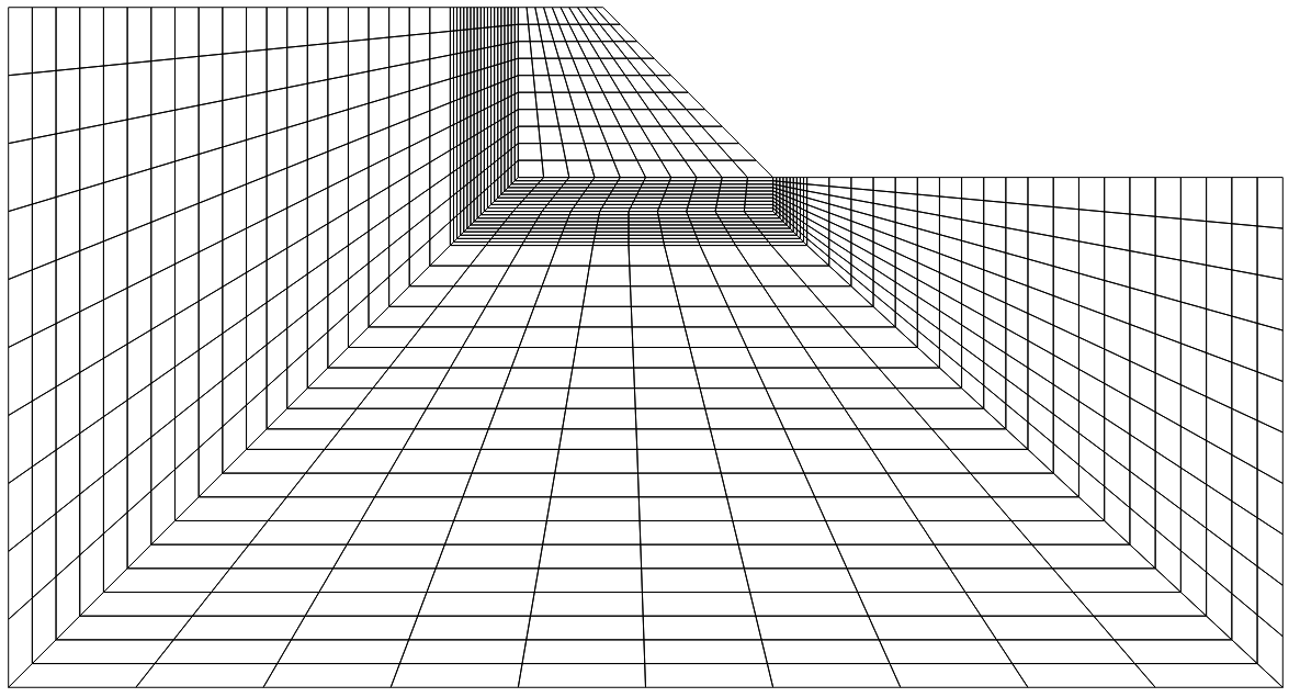
    newMesh["Wireframe"]

enter image description here

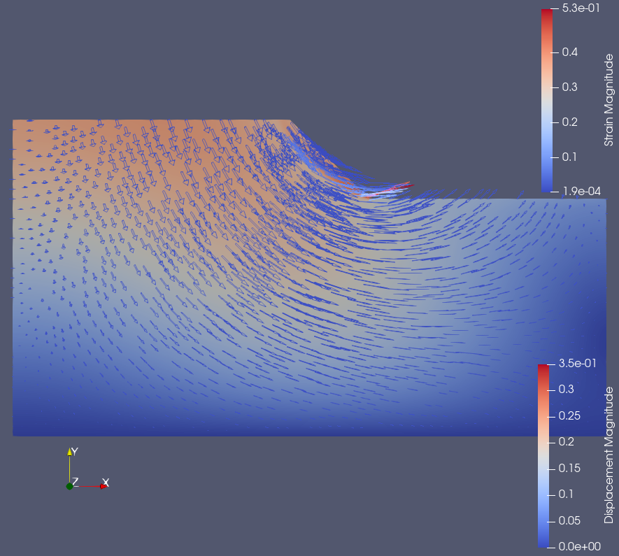
FEM results:

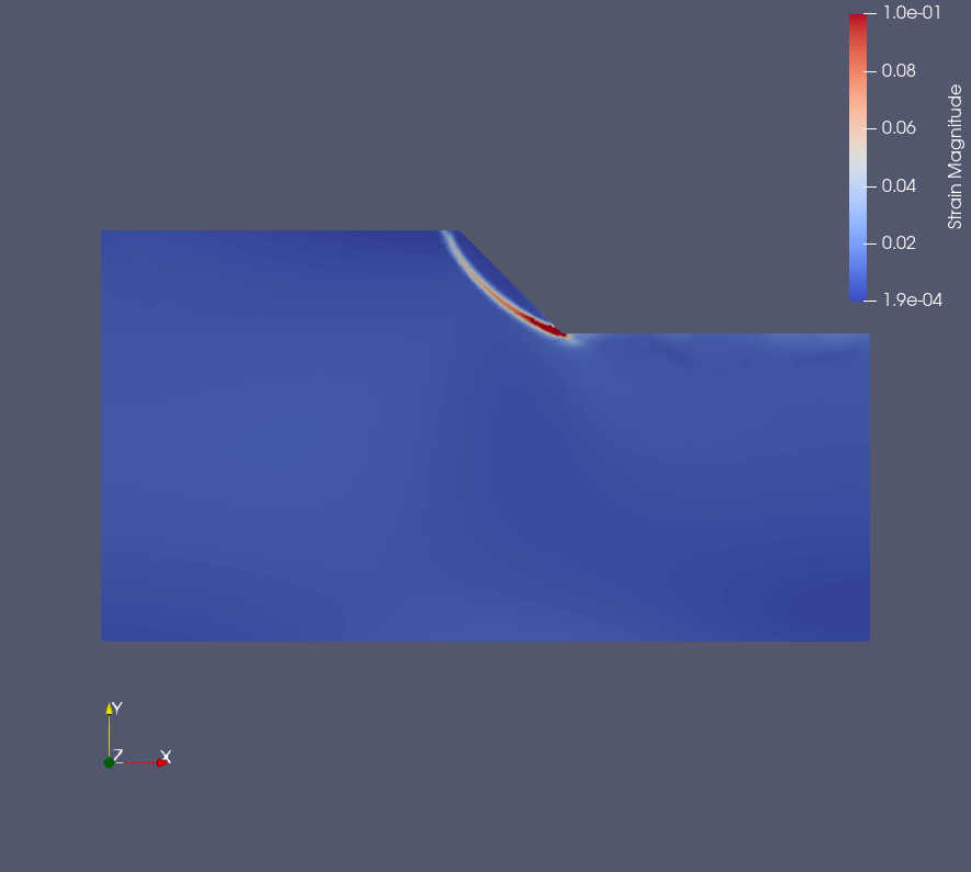
Here are the elastoplastic (Mohr-Coulomb model) simulation results for the slope stability problem considering only body forces.

Displacement Field (magnitude):

enter image description here

Elastic strains (magnitude)

enter image description here

$\endgroup$

Your Answer

By clicking “Post Your Answer”, you agree to our terms of service and acknowledge you have read our privacy policy.

Not the answer you're looking for? Browse other questions tagged or ask your own question.