9
$\begingroup$

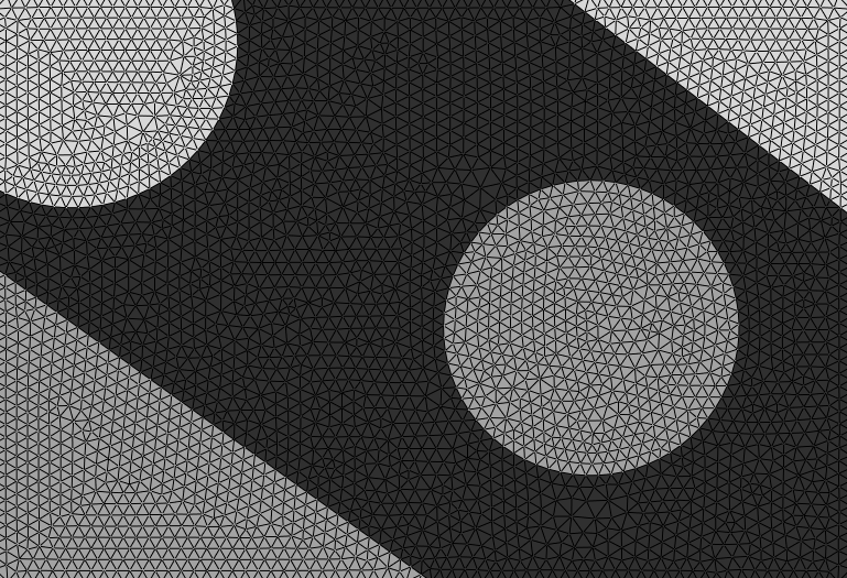
I want to mesh a figure which contains three different materials (organic-based materials and polymers) using Mathematica.

Namely:

Black color: material A

White color: material B

Grey color: material C

in the attachment you will see this figure

enter image description here

I have used ImageMesh[] command in Mathematica, and it does not work.

After the ImageMesh operation we can see such mesh type: enter image description here

Or looks like this https://i.sstatic.net/mHFNK.png

$\endgroup$
7
  • 2
    $\begingroup$ Can you explain what you want the result to look like? How do the colours affect the mesh? What do you mean by "... it does not work." - in what way does it not produce the result you want. $\endgroup$
    – flinty
    Commented Aug 20, 2021 at 16:15
  • $\begingroup$ @flinty I have improved the question! $\endgroup$
    – Libo Yan
    Commented Aug 20, 2021 at 16:25
  • $\begingroup$ The mesh image you posted looks nothing like the white/gray/black image so I'm more confused now. $\endgroup$
    – flinty
    Commented Aug 20, 2021 at 16:26
  • $\begingroup$ @flinty the color is changed to {Black, Gray, White}. $\endgroup$
    – Libo Yan
    Commented Aug 20, 2021 at 16:29
  • $\begingroup$ The image has some small white areas in the gray and black regions. Do you want those white areas as part of the "white" mesh? Or consider those small white regions as part of the gray and black parts? $\endgroup$
    – tad
    Commented Aug 20, 2021 at 17:22

4 Answers 4

11
$\begingroup$

Combining separate meshes from each image component works well for showing the mesh as a graphics. But the combined meshes don't always match at the boundaries between materials and can have tiny gaps. You can see these problems by zooming into the boundary areas in graphics of the combined meshes. They don't matter for visualization, but can be a problem if you want to use the mesh with NDSolve, e.g., solving for heat transfer through materials with different thermal conductivity.

To avoid gaps, it's best to mesh as a single region with internal boundaries between the different materials, as described in the documentation tutorial FEMDocumentation/tutorial/ElementMeshCreation, in the sections "Element Meshes with Subregions" and "Markers".

One way to get the boundaries is from the clustering components in Rom38's answer, using the "Contours" property of ComponentMeasurements. Then convert these boundaries into the form required by ToBoundaryMesh:

Needs["NDSolve`FEM`"];

img = Import["https://i.sstatic.net/zD7Ar.jpg"];

Module[{components, boundaries, coords, elements, bmesh, 
  pointInEachRegion, reg, parts, markers},

 components = ClusteringComponents[img, 3];
 
 boundaries = 
  Flatten[
   Values@
    ComponentMeasurements[components, "Contours", All, 
     "ComponentAssociation"]];
 
 (* points appearing in the boundaries *)
 coords = Flatten[Cases[boundaries, Line[pts_] :> pts], 1];
 coords = DeleteDuplicates[coords];
 
 (* replace boundary points by indices into list of coordinates *)
 boundaries = 
  boundaries /. 
   Line[pts_] :> 
    Line[
     pts /. 
      p : {_?NumberQ, _?NumberQ} :> FirstPosition[coords, p][[1]]];

 (* remove repeated successive coordinates *)
 boundaries = 
  boundaries /. 
   Line[pts_] :> 
    Line[pts //. {first___, a_, a_, rest___} :> {first, a, rest}];
 
 (* convert boundary lines into mesh elements *)
 elements = 
  boundaries /. Line[pts_List] :> LineElement[Partition[pts, 2, 1]];
 
 (* mesh with internal boundaries between the materials *)
 bmesh = 
  ToBoundaryMesh["Coordinates" -> coords, 
   "BoundaryElements" -> elements];
 
 (* random point in each connected part of each component to specify markers in the mesh *)
 SeedRandom[123];
 pointInEachRegion = 
  Table[reg = 
    ImageMesh[
     Image[components /. Thread[DeleteCases[Range[3], i] -> 0]]];
   parts = ConnectedMeshComponents[reg];
   RandomPoint /@ parts, {i, 3}];
 
 (* markers indicating each material, in this case, markers 1, 2 and 3 for the three components *)
 markers = 
  Flatten[Table[{#, i} & /@ pointInEachRegion[[i]], {i, 3}], 1];

(* extend boundary mesh to full mesh with markers for each material *)
     ToElementMesh[bmesh, "RegionMarker" -> markers]
 ]

This code creates a single ElementMesh for the whole region, with small mesh elements near the boundary. You can adjust mesh size with options to ToElementMesh.

NDSolve can use this mesh, e.g., to compute heat transport, with material properties, such as thermal conductivity, specified by the value of ElementMarker, which in this case has the values 1, 2 and 3.

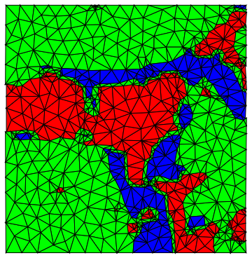
Visualize the mesh with colors indicating the marker associated with each mesh triangle:

%["Wireframe"[PlotRangePadding -> None, 
  "MeshElementStyle" -> (Directive[FaceForm[#], 
       EdgeForm[Opacity[.2]]] & /@ {Lighter@Red, Green, LightBlue})]]
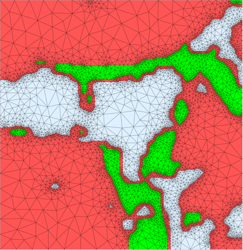
mesh with markers indicating different materials

One possible issue with this approach is the boundary between materials returned by ComponentMeasurements is fairly jagged in some places. Smoother boundaries between materials would require a different approach. E.g., use a contour plot of the image data, extract the lines of the contours and then convert them to the form required for ToBoundaryMesh, as done in the above code for boundaries from ComponentMeasurements. This will require more manual adjustment of parameters, e.g., to pick the contours.

p.s., if the image is noisy, you can filter the image first. E.g., with MedianFilter or a filter that preserves edges better, such as BilateralFilter.

$\endgroup$
1
  • $\begingroup$ thanks! I will post a question about how to filter the image using Mathematica. $\endgroup$
    – Libo Yan
    Commented Aug 22, 2021 at 19:30
10
$\begingroup$

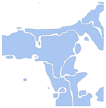
I guess, the cc=ClusteringComponents[img, 3] is good here:

enter image description here

It gives you an array where point of certain color is marked by numbers 1-2-3 (I asked for just three regions). You can select any of them by replacement of all rest by 0 and make the desired ImageMesh of the segment:

s1=cc /. {1 -> 0, 2 -> 0};
s2=cc /. {2 -> 0, 3 -> 0};
s3=cc /. {1 -> 0, 3 -> 0};
ImageMesh[Image@s1] 

enter image description here

Similarly, you can make the meshes for s2 and s3.

The combined mesh can be made from initial cc:

ImageMesh[Image@cc]

enter image description here

m1 = DiscretizeRegion@ImageMesh[Image@s1];
m2 = DiscretizeRegion@ImageMesh[Image@s2];
m3 = DiscretizeRegion@ImageMesh[Image@s3];
Graphics[{EdgeForm[Black], Red, m1, Green, m2, Blue, m3}]

enter image description here

$\endgroup$
6
  • $\begingroup$ thanks, I would ask, how to mesh each material areas. and merge three materials? $\endgroup$
    – Libo Yan
    Commented Aug 20, 2021 at 17:25
  • 1
    $\begingroup$ @LiboYan, I've updated the answer. $\endgroup$
    – Rom38
    Commented Aug 20, 2021 at 17:37
  • $\begingroup$ we need to merge materials after the meshing step: e.g. i.sstatic.net/mHFNK.png $\endgroup$
    – Libo Yan
    Commented Aug 20, 2021 at 17:55
  • 1
    $\begingroup$ @LiboYan, man, I show you the special points but further you should use the general ways by youself.. Try Graphics[{Red,mesh1, Green, mesh2, Blue, mesh3}] for nice figures or use meshes for calculations. There meshXX are results of each ImageMesh. Also you can use DiscretizeRegion for meshes to make the triangular net.. $\endgroup$
    – Rom38
    Commented Aug 20, 2021 at 18:19
  • $\begingroup$ @LiboYan, it seems that this is a separate question entirely. Please, take care to discern between the various parts of your inquiries and realize when each of them are separate questions that are best asked as a new question post. $\endgroup$ Commented Aug 20, 2021 at 21:17
6
$\begingroup$

It sounds like maybe you want a mesh for each colour (?)

img = Import["https://i.sstatic.net/zD7Ar.jpg"];
cols = {Black, Gray, White};
cq = ColorQuantize[img, cols, Dithering -> False]
ImageMesh[ColorReplace[cq, {_ -> Black, # -> White}]] & /@ cols

meshes

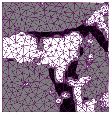
Unfortunately RegionUnion doesn't work, even on the triangulated meshes, but it's still possible to present the meshes with the wireframe:

Graphics[{EdgeForm[Darker@Purple], 
  Riffle[cols, TriangulateMesh /@ meshes]}]

meshes

$\endgroup$
1
  • 1
    $\begingroup$ how to mesh each figure. and merge three parts? $\endgroup$
    – Libo Yan
    Commented Aug 20, 2021 at 16:31
6
$\begingroup$
img = Import["https://i.sstatic.net/zD7Ar.jpg"];
whiteImg = MorphologicalBinarize[img, 0.9];
blackImg = MorphologicalBinarize[ColorNegate@img, 0.7];
blackgrayMesh = ImageMesh[ColorNegate@whiteImg];
whiteMesh = ImageMesh[whiteImg];
blackMesh = ImageMesh[blackImg];
grayMesh = RegionDifference[blackgrayMesh, blackMesh];
Needs["NDSolve`FEM`"]
ToElementMesh[whiteMesh][
  "Wireframe"["MeshElementStyle" -> FaceForm[White]]];
ToElementMesh[grayMesh][
  "Wireframe"["MeshElementStyle" -> FaceForm[Green]]];
ToElementMesh[blackMesh][
  "Wireframe"["MeshElementStyle" -> FaceForm[Red]]];
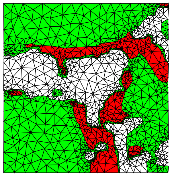
Show[%%%, %%, %]

enter image description here

Edit

Another possible way.

img = Import["https://i.sstatic.net/zD7Ar.jpg"];
result = DominantColors[img, 
  Automatic, {"CoverageImage", "MaskCoverage", "Color"}, 
  Method -> Automatic]
{gray, white, black, unknow} = ImageMesh /@ result[[All, 1]];
Needs["NDSolve`FEM`"]
ToElementMesh[white][
  "Wireframe"["MeshElementStyle" -> FaceForm[White]]];
ToElementMesh[gray][
  "Wireframe"["MeshElementStyle" -> FaceForm[Green]]];
ToElementMesh[black]["Wireframe"["MeshElementStyle" -> FaceForm[Red]]];
ToElementMesh[unknow][
  "Wireframe"["MeshElementStyle" -> FaceForm[Cyan]]];
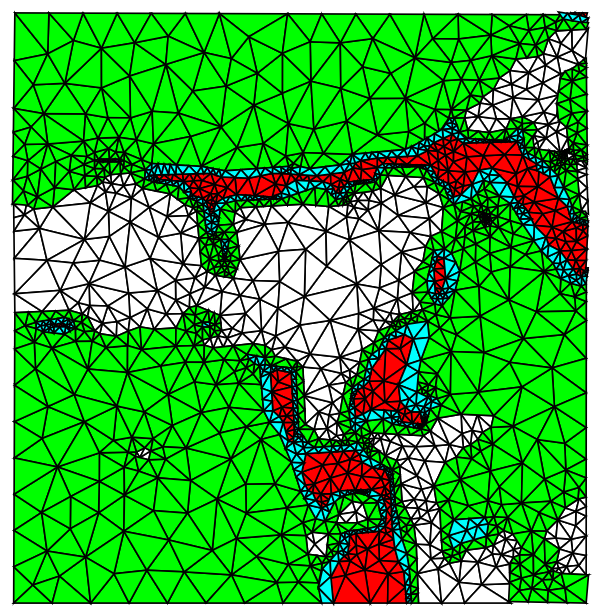
Show[%%%%, %%%, %%, %]

enter image description here

$\endgroup$
2
  • $\begingroup$ thanks! how to improve the result, because this code generates some new grey materal areas between white and black materials, which are not given in the original figure. $\endgroup$
    – Libo Yan
    Commented Aug 21, 2021 at 10:59
  • $\begingroup$ img = Import["https://i.sstatic.net/zD7Ar.jpg"]; result = DominantColors[img, 3, {"CoverageImage", "MaskCoverage", "Color"}, Method -> Automatic] $\endgroup$
    – cvgmt
    Commented Aug 21, 2021 at 12:10

Your Answer

By clicking “Post Your Answer”, you agree to our terms of service and acknowledge you have read our privacy policy.

Not the answer you're looking for? Browse other questions tagged or ask your own question.