5
$\begingroup$

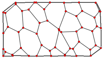
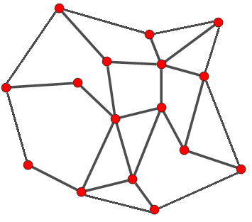
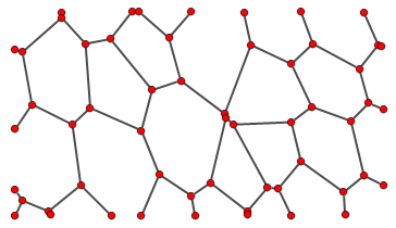
Consider the following graph g

enter image description here

I want to "close" it by adding the following edges

enter image description here

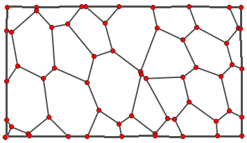
Alternatively, I would also be happy with something like

enter image description here

where I've added four "corner" vertices.

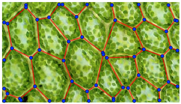
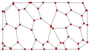
Now, this question is, in a way, a follow up to this answer, where I initially have a picture on which I draw a graph, as follows

enter image description here

Is it possible to turn the picture into a rectangle-shaped graph and then join them in somehow? This would lead to something like the second example.

Alternatively, I also thought about simply uniting 1-degree vertices that are close to each other, creating the first example graph.

In the end, I want a graph that defines a mesh, thus the need of "closing" the graph in this fashion. Ideally, I want KVertexConnectedGraphQ[g] = True for the closed graph.

Any ideas?

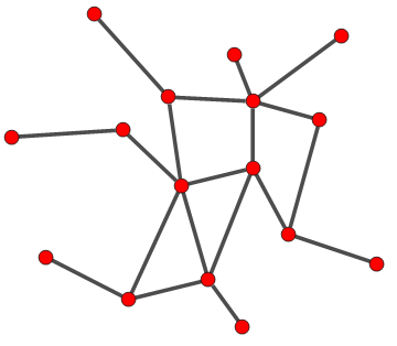
Edit 1: Note that my goal is to be able to do this for general graphs. For example, considering the graph

enter image description here

I want to get something like

enter image description here

I guess using something like ConvexHull (which doesn't correspond to what is drawn) in some matter could help my goal, but at this point I'm entirely sure how.

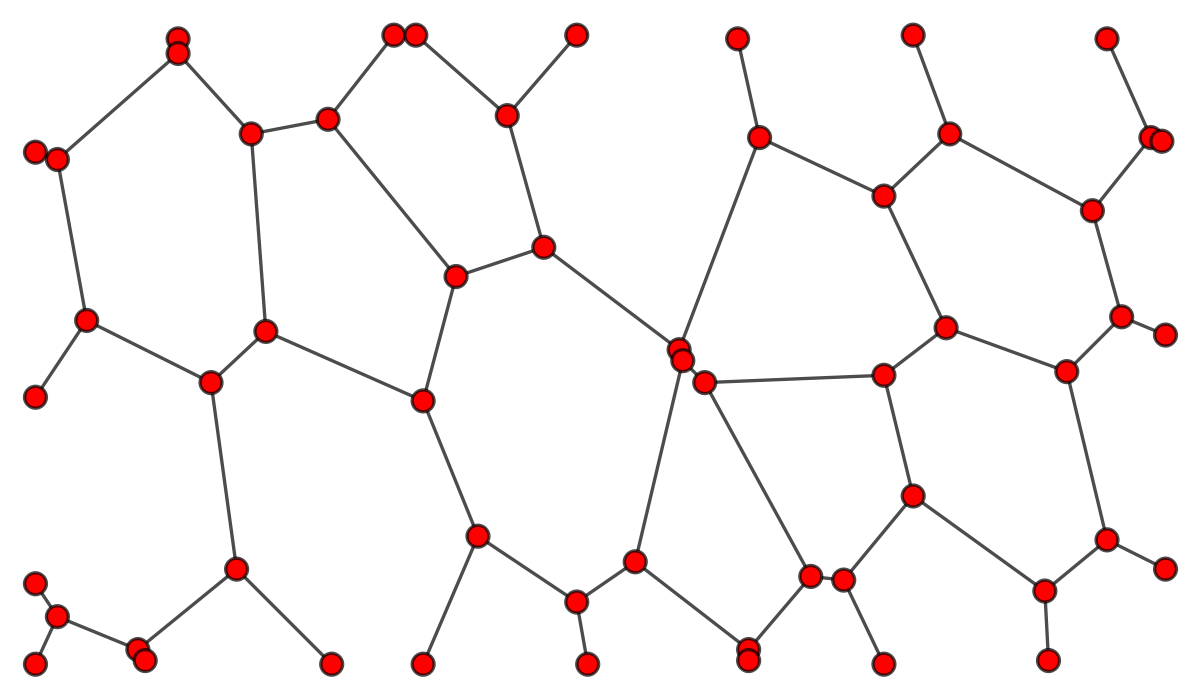
Edit 2: In order to be more practical consider the graph given by

g = Graph[{1 \[UndirectedEdge] 10, 2 \[UndirectedEdge] 9, 
   3 \[UndirectedEdge] 9, 4 \[UndirectedEdge] 12, 
   5 \[UndirectedEdge] 8, 6 \[UndirectedEdge] 13, 
   7 \[UndirectedEdge] 14, 8 \[UndirectedEdge] 11, 
   8 \[UndirectedEdge] 17, 9 \[UndirectedEdge] 20, 
   10 \[UndirectedEdge] 11, 10 \[UndirectedEdge] 21, 
   11 \[UndirectedEdge] 25, 12 \[UndirectedEdge] 18, 
   12 \[UndirectedEdge] 19, 13 \[UndirectedEdge] 18, 
   13 \[UndirectedEdge] 27, 14 \[UndirectedEdge] 15, 
   14 \[UndirectedEdge] 19, 16 \[UndirectedEdge] 17, 
   17 \[UndirectedEdge] 23, 18 \[UndirectedEdge] 24, 
   19 \[UndirectedEdge] 22, 20 \[UndirectedEdge] 21, 
   20 \[UndirectedEdge] 27, 21 \[UndirectedEdge] 34, 
   22 \[UndirectedEdge] 26, 22 \[UndirectedEdge] 29, 
   23 \[UndirectedEdge] 31, 23 \[UndirectedEdge] 33, 
   24 \[UndirectedEdge] 29, 24 \[UndirectedEdge] 30, 
   25 \[UndirectedEdge] 31, 25 \[UndirectedEdge] 34, 
   27 \[UndirectedEdge] 28, 28 \[UndirectedEdge] 32, 
   28 \[UndirectedEdge] 38, 29 \[UndirectedEdge] 37, 
   30 \[UndirectedEdge] 32, 30 \[UndirectedEdge] 35, 
   31 \[UndirectedEdge] 39, 32 \[UndirectedEdge] 41, 
   34 \[UndirectedEdge] 36, 35 \[UndirectedEdge] 42, 
   35 \[UndirectedEdge] 44, 36 \[UndirectedEdge] 45, 
   36 \[UndirectedEdge] 54, 37 \[UndirectedEdge] 40, 
   37 \[UndirectedEdge] 44, 38 \[UndirectedEdge] 45, 
   38 \[UndirectedEdge] 48, 39 \[UndirectedEdge] 47, 
   39 \[UndirectedEdge] 53, 41 \[UndirectedEdge] 42, 
   41 \[UndirectedEdge] 48, 42 \[UndirectedEdge] 56, 
   43 \[UndirectedEdge] 46, 44 \[UndirectedEdge] 51, 
   45 \[UndirectedEdge] 55, 46 \[UndirectedEdge] 47, 
   46 \[UndirectedEdge] 52, 47 \[UndirectedEdge] 49, 
   48 \[UndirectedEdge] 50},
  VertexCoordinates -> {{102.5`, 175.5`}, {84.5`, 152.5`}, {108.5`, 
     175.5`}, {133.5`, 153.5`}, {152.5`, 175.5`}, {244.5`, 
     175.5`}, {254.5`, 148.5`}, {43.5`, 174.5`}, {43.5`, 
     170.5`}, {196.5`, 174.5`}, {202.5`, 147.5`}, {297.5`, 
     174.5`}, {309.5`, 147.5`}, {63.5`, 148.5`}, {10.5`, 
     141.5`}, {143.5`, 117.5`}, {119.5`, 109.5`}, {67.5`, 
     94.5`}, {236.5`, 131.5`}, {293.5`, 127.5`}, {180.5`, 
     89.5`}, {312.5`, 146.5`}, {4.5`, 143.5`}, {18.5`, 
     97.5`}, {253.5`, 95.5`}, {301.5`, 98.5`}, {110.5`, 
     75.5`}, {313.5`, 93.5`}, {286.5`, 83.5`}, {52.5`, 80.5`}, {4.5`, 
     76.5`}, {236.5`, 82.5`}, {181.5`, 86.5`}, {187.5`, 
     80.5`}, {168.5`, 31.5`}, {297.5`, 37.5`}, {244.5`, 
     49.5`}, {59.5`, 29.5`}, {216.5`, 27.5`}, {125.5`, 
     38.5`}, {225.5`, 26.5`}, {280.5`, 23.5`}, {152.5`, 
     20.5`}, {110.5`, 3.5`}, {313.5`, 29.5`}, {199.5`, 7.5`}, {32.5`, 
     7.5`}, {85.5`, 3.5`}, {236.5`, 3.5`}, {4.5`, 25.5`}, {10.5`, 
     16.5`}, {281.5`, 4.5`}, {155.5`, 3.5`}, {4.5`, 3.5`}, {34.5`, 
     4.5`}, {199.5`, 4.5`}},
  VertexSize -> 3 {1, 1}, VertexStyle -> Red, 
  EdgeStyle -> Directive[Black]]

which yields the first graph g. Then, the code

hm = ConvexHullMesh[
      Transpose[
Select[{GraphEmbedding[g], VertexDegree[g]} // 
      Transpose, #[[2]] == 1 &]][[1]]]
gb = Graph[hm["Edges"], VertexCoordinates -> MeshCoordinates[hm], 
  VertexSize -> 3 {1, 1}, VertexStyle -> Red, 
  EdgeStyle -> Directive[Black]]

yields

enter image description here

Now, how do I merge both graphs? I tried GraphUnion, but I would need the correct VertexCoordinates. Could it be simply an ordering problem? Any suggestion?

$\endgroup$
8
  • $\begingroup$ Please provide the graph data so we can help you. $\endgroup$ Commented Mar 16, 2020 at 20:12
  • $\begingroup$ The data can be found in the linked answer. $\endgroup$
    – sam wolfe
    Commented Mar 16, 2020 at 20:14
  • $\begingroup$ Also, this is but an example graph, I want to be able to do it more generally. I will edit the question in order to make this point more clear. $\endgroup$
    – sam wolfe
    Commented Mar 16, 2020 at 20:15
  • $\begingroup$ It doesn't really matter, but I provided the full data anyway (Edit 2). Now I simply need to join both graphs. Please take a look. $\endgroup$
    – sam wolfe
    Commented Mar 16, 2020 at 20:56
  • $\begingroup$ What is your definition of a graph? What is your definition of "closed" graph? $\endgroup$
    – Helena
    Commented Mar 17, 2020 at 10:23

3 Answers 3

6
$\begingroup$

This problem isn't really related to graphs. Graphs, by definition, only contain connectivity information. What you are asking for is a geometry problem, not a graph theory problem.

What you show in your example figure is a convex hull. ConvexHullMesh can compute it.

$\endgroup$
6
  • $\begingroup$ Yes, I figured out that could be the way to go (see edit). But can I apply the ConvexHullMesh to a graph? $\endgroup$
    – sam wolfe
    Commented Mar 16, 2020 at 20:24
  • 2
    $\begingroup$ No. As I said, it's a geometrical operation. If you post sample data, I will show you how to do it, and actually augment a Graph with new edges. $\endgroup$
    – Szabolcs
    Commented Mar 16, 2020 at 20:47
  • $\begingroup$ Please look at Edit 2. I managed to get what I wanted, now I simply need to join the two graphs. $\endgroup$
    – sam wolfe
    Commented Mar 16, 2020 at 20:55
  • 1
    $\begingroup$ I will, tomorrow. Sorry, too tired. $\endgroup$
    – Szabolcs
    Commented Mar 16, 2020 at 21:01
  • $\begingroup$ @samwolfe You got your answer from kglr. I would have likely come up with something very similar. $\endgroup$
    – Szabolcs
    Commented Mar 17, 2020 at 9:42
5
$\begingroup$
posToVertex = AssociationThread[GraphEmbedding[g], VertexList[g]];

newEdges =  Map[posToVertex, MeshPrimitives[ConvexHullMesh[GraphEmbedding[g]], 1] /. 
      Line -> Apply[UndirectedEdge], {-2}];

EdgeAdd[g, newEdges]

enter image description here

$\endgroup$
3
  • $\begingroup$ This is a good answer, but I'm still not getting KVertexConnectedGraphQ[g, 2] = True. Any idea why? $\endgroup$
    – sam wolfe
    Commented Mar 17, 2020 at 12:49
  • $\begingroup$ I am still getting vertices with degree one, when evaluating VertexDegree[g]. $\endgroup$
    – sam wolfe
    Commented Mar 17, 2020 at 12:53
  • $\begingroup$ It seems to me that what is happening is that the ConvexHullMesh naturally misses some degree-1 vertices and your graph simply has the illusion that there are no degree-1 vertices. $\endgroup$
    – sam wolfe
    Commented Mar 17, 2020 at 13:18
1
$\begingroup$

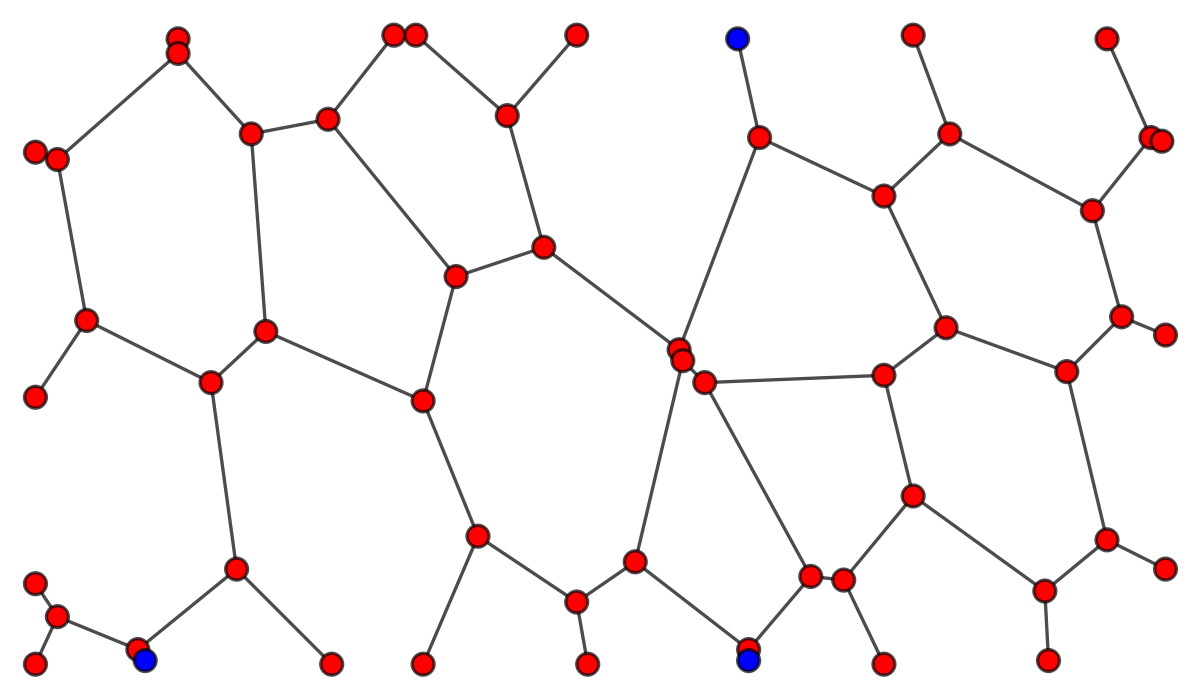
The graph g in the example:

enter image description here


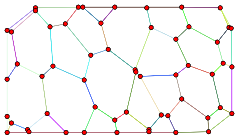
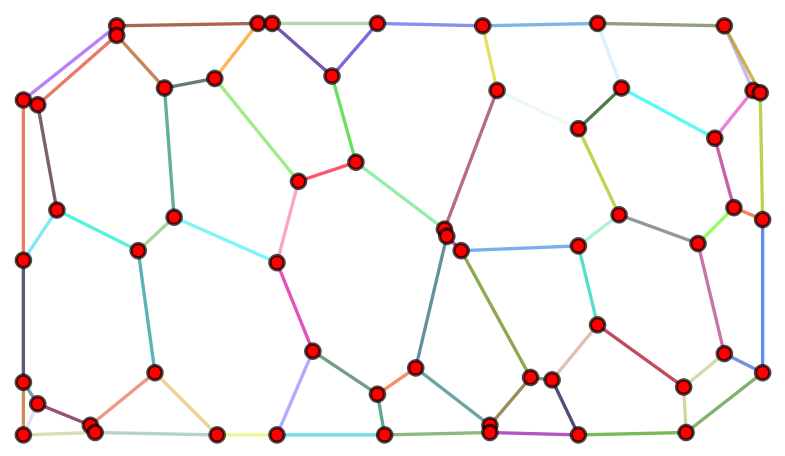
With direct application of ConvexHullMesh and usage of the generated Lines there are missing edges at the boundary. The graph below colors edges randomly but as we see there are many supposed edges at the boundary that are actually the same edge as they have the same color. They are simply long edges that traverse the vertices due to the imposed geometry for the graph.

enter image description here

With the codes below all edges are included depending on the definition one takes.

Definition A

The boundary is the set of degree 1 vertices that are not encircled by other vertices in the geometrical graph embedding."

In other words they are the outer vertices that are of degree 1. This definition works nicely in the example above as most of the outer vertices are of degree 1.

Definition B

The boundary is the set of vertices that belong to the convex hull.

Note that this might not be your preferred definition given that you gave a non convex example. In particular some of the outer degree 1 vertices will not be included in the boundary and so you are not guaranteed that KVertexConnectedGraphQ[graph, 2]. In particular this will not be the case below for the convex boundary.

Definition A : Focus on the degree 1 vertices

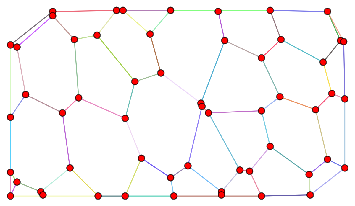
The image below is generated from the code in the last section.

Note that randomly coloring the edges a few times, accidental same color adjacent edges are removed.

enter image description here

Definition B: focus on the convex hull

The change is minor in this case as only the blue vertices are not on the convex hull. The change would be more significant for a "less convex" graph:

enter image description here

Nevertheless these are the edges for this definition:

Note that where the vertices are not included the color is the same on either side as the edge simply traverses the vertex without any connection. Those degree one vertices are not connected to the edge and so KVertexConnectedGraphQ[graph, 2] is false.

enter image description here


Outline

  • Issue with direct application of ConvexHull

  • Possible solution


Issue with direct application of ConvexHull

TL;DR : The line segments from ConvexHull seem to pass through points that rest on the same line. Hence there are missing edges when one just adds the line segments.

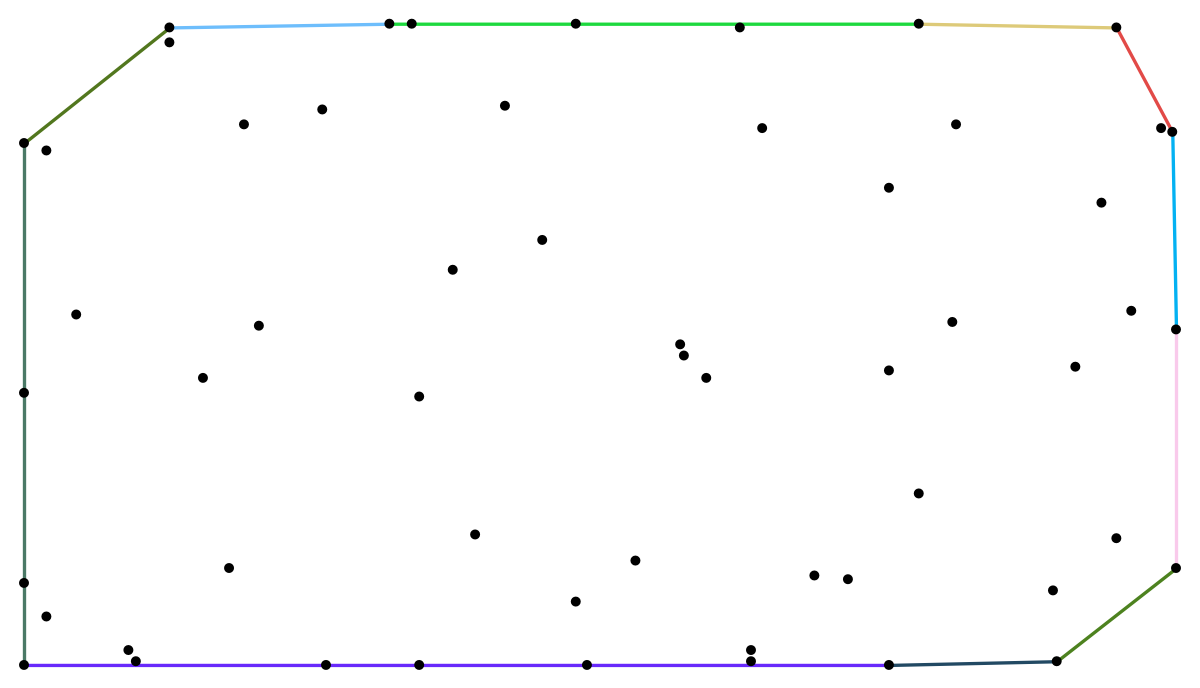
From what I tested, the convex hull mesh does not seem to produce all the edges between graph vertices. See the image below that shows the added line segments from the convex hull:

{GraphEmbedding[g] // ConvexHullMesh // MeshPrimitives[#, 1] & // 
    Map[{RandomColor[], #} &], GraphEmbedding[g] // Map[Point]} // 
  Catenate // Graphics

enter image description here

This can also be checked with the graph:

HighlightGraph[new, Style[#, RandomColor[]] & /@ EdgeList@new]

enter image description here

There are colors that traverse vertices at the boundary.

Also

KVertexConnectedGraphQ[new, 2]

(* False *)

which OP does not seem to want.


Possible solution

TL;DR: Extract vertices at the boundary either by their degree or whether they belong to the convex hull (may lead to different results depending on the graph), use FindCurvePath and PathGraph to connect them and then add them to the original graph with a graph position to geometrical postion mapping.

Method 1: Exploit the vertex degree of the vertices at the boundary.

All of the degree 1 vertices in the example provided are "outer vertices" hence we shall not impose the constraint that the vertex should not be encircled by others. For another graph one might have to add the no encircling constraint.

Degree 1 vertices can be extracted using:

Note: (…=\[Ellipsis])

boundary…vertices = 
 VertexList[g, _?(VertexDegree[g, #] == 1 &)];

Their geometric positions can be found using the rule:

VertexPos = Thread[VertexList[g] -> GraphEmbedding[g]];

Note: (⎵=\[UnderBracket])

boundary…vertices⎵positions = 
 boundary…vertices /. VertexPos;

One may order these vertices along a path using FindCurvePath

path…ordering = 
  FindCurvePath[boundary…vertices⎵positions];

path = boundary…vertices⎵positions[[path…ordering[[1]]]];

Then one may construct edges from those ordered points using PathGraph and EdgeList. Note that we first had to order the edges before using PathGraph.

path⎵edges = path // PathGraph // EdgeList;

Those are written as spatial points we have to convert them back to vertex positions by inverting VertexPos above. We then add those edges to the original graph:

completed…graph = EdgeAdd[g, path⎵edges /. Reverse /@ VertexPos];

We can check the result with:

HighlightGraph[completed…graph, 
Style[#, RandomColor[]] & /@ EdgeList@completed…graph]

Note: some edges at the boundary might randomly have a similar color, evaluate the code again to change colors and check that the edges no longer have the same color.

enter image description here

KVertexConnectedGraphQ[completed…graph, 2]

(* True *)

Method 2: Extract points from the boundary of the convex hull.

Note : Mainly only the code for boundary…vertices⎵positions is changed, the rest is copy pasted for those that did not read method 1 except for the end when I test KVertexConnectedGraphQ[completed…graph, 2] to be false. I will indicate when the rest is copy pasted other than the KVertexConnectedGraphQ[completed…graph, 2] test.

The boundary of the convex hull as a list lines:

lines = ConvexHullMesh[GraphEmbedding[g]] // MeshPrimitives[#, 1] &;

Geometric positions of vertices in the graph can be found using the rule:

VertexPos = Thread[VertexList[g] -> GraphEmbedding[g]];

A function that checks whether a point belongs to the boundary:

boundaryPoint[point_] := AnyTrue[lines, RegionMember[#, point] &];

Select the positions of boundary vertices in the graph embedding :

boundary…vertices⎵positions = 
Select[VertexList[g] /. VertexPos, boundaryPoint];

The following is identical to method 1 and so has been copy pasted for convenience:

One may order these vertices along a path using FindCurvePath

path…ordering = 
  FindCurvePath[boundary…vertices⎵positions];

path = boundary…vertices⎵positions[[path…ordering[[1]]]];

Then one may construct edges from those ordered points using PathGraph and EdgeList. Note that we first had to order the edges before using PathGraph.

path⎵edges = path // PathGraph // EdgeList;

Those are written as spatial points we have to convert them back to vertex positions by inverting VertexPos above. We then add those edges to the original graph:

completed…graph = EdgeAdd[g, path⎵edges /. Reverse /@ VertexPos]

We can check the result with:

HighlightGraph[completed…graph, 
Style[#, RandomColor[]] & /@ EdgeList@completed…graph]

Note: some edges at the boundary might randomly have a similar color, evaluate the code again to change colors and check that the edges no longer have the same color.

enter image description here

KVertexConnectedGraphQ[completed…graph, 2]

(* False *)

$\endgroup$

Your Answer

By clicking “Post Your Answer”, you agree to our terms of service and acknowledge you have read our privacy policy.

Not the answer you're looking for? Browse other questions tagged or ask your own question.