3
$\begingroup$

Inspired by Henry Segerman's developing fractal curves, I decided to try to convince Mathematica to do something similar. The inspiration for cf, f, and g below came from How to make this Dragon Curve?.

cf = Compile[{{M, _Real, 2}, t, a}, 
   With[{A = M[[1]], B = M[[2]]}, 
    With[{P = (A + B + a t Cross[B - A])/2}, {{A, P}, {B, P}}]], 
   RuntimeAttributes -> Listable];

f[n_, a_] := Flatten[Nest[cf[#, 1, a] &, {{{0, 0}, {1, 0}}}, Floor@n], Floor@n];
g[n_, a_] := Flatten[cf[f[n, a], FractionalPart[n], a], 1];

iterations = 10;
ang = 1;
widthscale = GoldenRatio;
functionPoints3D[z_] := 
  Map[Append[(1.5)^(Sqrt[z])], Flatten[widthscale g[z, ang], 1]];
pointlist = Table[functionPoints3D[n], {n, 0, iterations, .1}];
Graphics3D[BezierCurve[Partition[Flatten[pointlist, 1], 2]]]

I haven't been able to figure out how to turn this into a mesh or extrude this into something that could be exported as a printable object. I've tried several things, but none of them have worked.

Bonus if there's a way to make the corners more curved (akin to c or s shapes instead of right angles).

Edit (2/29): Here's a cheated image of the "solid" using tubes spaced .01 apart to give the idea of what it will look like once done. Once I get it all finished, I will definitely post a picture of the printed object. For now, here's the teaser:

Roughly what it will look like

$\endgroup$
6
  • $\begingroup$ Wow, beautiful. Hm. It should be straight-forward to put a quadrilateral or triangle mesh onto the geometry and do the rounding stuff once for each level, the pts of the curve are written into a separate list in correct order. Can you do that first? $\endgroup$ Commented Feb 26, 2020 at 15:17
  • $\begingroup$ For example, corresponding to pointlist[[20]] the point set I would like to have is { {0.`, 0.`, 1.748739218545116`}, {0.040450849718747316`, 0.7685661446562001`, 1.748739218545116`}, {0.8090169943749475`, 0.8090169943749475`, 1.748739218545116`}, {0.8494678440936947`, 0.040450849718747316`, 1.748739218545116`}, {1.618033988749895`, 0.`, 1.748739218545116`} }. $\endgroup$ Commented Feb 26, 2020 at 15:17
  • $\begingroup$ Well, that's in principle the idea. But at later iterations, the curves touch themselves and it would be easiest to cope with that with the points in a line are ordered "correctly", i.e., in the order they are traversed by the polyline. $\endgroup$ Commented Feb 26, 2020 at 19:10
  • $\begingroup$ If you have that, you can take the points of the $i$-th and $(i+1)$-st list and connect them easily: If both lists have the same length then the the first two of each list make a quad; then the 2nd dn 3rd one and so on. The other case is that the $(i+1)$-st has twice as many edges than the $i$-th one. That's because each edge in the $i$-th list is split into two. That can be resolved by three triangles. $\endgroup$ Commented Feb 26, 2020 at 19:13
  • 1
    $\begingroup$ Accidentally deleted my previous comment... I thought they were ordered by the order they were traversed (the start is (0,0,z) in this) and I think this is the case, but I notice that I am also generating some repeated points on the end of the list somehow. Your last comment is absolutely correct, I was trying to think about how to connect the curves of differing numbers of points (which are the 0 mod 10 to 1 mod 10 pointlist elements). I'll give it a shot, but I haven't used the MeshRegion function before (which I'm assuming is the tool needed?). $\endgroup$
    – ryan.axiom
    Commented Feb 26, 2020 at 19:20

1 Answer 1

1
$\begingroup$

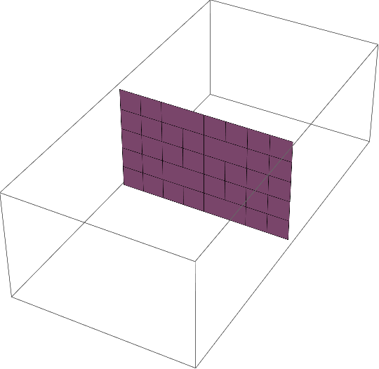
Here is an example how you can mesh the regular part of your curves:

n = 2^3;
m = 5;
h = 1/n;
newpointlist = Table[
   Subdivide[{0, 0, -i h}, {1, 0, -i h}, n],
   {i, 0, m}];
edges = Partition[#, 2, 1] & /@ 
   Partition[Range[(m + 1) (n + 1)], {n + 1}];
quads = Join @@ Join[
    Map[Reverse, edges[[;; -2]], {2}],
    edges[[2 ;;]],
    3
    ];
Graphics3D[
 GraphicsComplex[Join @@ newpointlist, Polygon[quads]]
 ]

enter image description here

Triangles can be obtained like this:

triangles = Riffle[quads[[All, 1 ;; 3]], quads[[All, {3, 4, 1}]]];
Graphics3D[
 GraphicsComplex[Join @@ newpointlist, Polygon[triangles]]
 ]

enter image description here

For the irregular part (where the number of edges doubles), you can try such a strategy:

n = 2^3;
m = 5;
h = 1/n;
newpointlist = Table[
   Subdivide[{0, 0, -i h}, {1, 0, -i h}, 2^i],
   {i, 0, m}];

triangles = Join @@ Transpose[{
     Transpose[{
       Flatten[idx[[1 ;; -2, 1 ;; -2 ;; 1]]],
       Flatten[idx[[2 ;; -1, 1 ;; -2 ;; 2]]],
       Flatten[idx[[2 ;; -1, 2 ;; -1 ;; 2]]]
       }],
     Transpose[{
       Flatten[idx[[1 ;; -2, 1 ;; -2 ;; 1]]],
       Flatten[idx[[2 ;; -1, 2 ;; -2 ;; 2]]],
       Flatten[idx[[1 ;; -2, 2 ;; -1 ;; 1]]]
       }],
     Transpose[{
       Flatten[idx[[1 ;; -2, 2 ;; -1 ;; 1]]],
       Flatten[idx[[2 ;; -1, 2 ;; -2 ;; 2]]],
       Flatten[idx[[2 ;; -1, 3 ;; -1 ;; 2]]]
       }]
     }
    ];

Graphics3D[{
  Point[Join @@ newpointlist],
  GraphicsComplex[Join @@ newpointlist, Polygon[triangles]]
  }]

enter image description here

I have to admit, it is a bit of fiddling. That is why I insisted on correct ordering. =)

After you have all triangles, put everything into a mesh region. You can round off averything nicely, e.g., with a few iterations of my function LoopSubdivide.

Afterwards, Export to STL or whatever format suits you. Usually, printing software can do the extrusion/thickening of the surface for you, but you can also find code for that job somewhere on this site...

$\endgroup$
3
  • $\begingroup$ That is amazing. I see exactly what you mean now about the ordering of the vertices. I looked at it for quite a while and have the first 129 vertices ordered (so through 7 full iterations) but at the moment, I don’t see a clear pattern (and manual ordering is not possible for many more iterations). I was using HighlightMesh since I could easily label the vertices (so I just had to follow the curve to get the ordering). It seems that I may have to come up with a different way to generate the points in order. Once I do though, this is perfect. $\endgroup$
    – ryan.axiom
    Commented Feb 27, 2020 at 3:43
  • $\begingroup$ I have a reasonable idea for ordering the vertices now. It would be easier to remove the intermediate layers but... With them my idea is straightforward but will take some time to get working. Perhaps I’ll get it over the weekend or early in the week and post the result once I do. Until then, I’ve found a way to cheat it to look like what it will be (using Tube with a small dz but it is too complex to export - 206k tubes or so). I tried but it was still working after 6 hours so... Today, I’ll update the question with an image of that output which is roughly what it should look like in the end. $\endgroup$
    – ryan.axiom
    Commented Feb 29, 2020 at 14:03
  • $\begingroup$ Yeah, interesting. Would be cool if you would post a picture of the printed model in the end. $\endgroup$ Commented Feb 29, 2020 at 15:32

Your Answer

By clicking “Post Your Answer”, you agree to our terms of service and acknowledge you have read our privacy policy.

Not the answer you're looking for? Browse other questions tagged or ask your own question.