Update 3
This is my final update except for typo corrections. I hope it provides a useful answer to the OP's question.
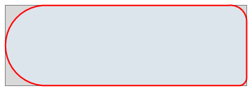
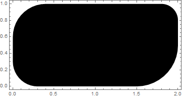
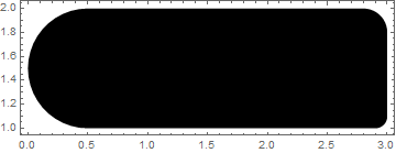
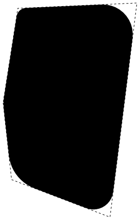
I don't believe the OP's problem can be solved by fooling around with RoundingRadius. I think one needs to write a function that will generate a polygon that Graphics will render as a NURC (Non-Uniform-Rounded-Corners) rectangle and which will behave as such when given to the various region functions.
Requirements
My goal is to implement a function that returns a polygon that will be rendered in graphics as a rectangle which can have non-uniform rounded corners.
Arguments
First two arguments are the same as for Rectangle: {xmin, ymin}, {xmax, ymax}.
Function should be able to build a rectangle with normal sharp corners.
Third argument is a list of the four corner radii: {rtl, rtr, rbl, rbr}.
rtl is the radius of the top-left corner.
rtr is the radius of the top-right corner.
rbl is the radius of the bottom-left corner.
rbr is the radius of the bottom-right corner.
Fourth argument, n, is the number of line segments making up the quarter circles composing the corners.
Exception: a corner with radius zero ignores this argument and consists of a single point.
Default value is 10.
No optional arguments
Argument consistency
First two arguments
Same consistency requirements as Rectangle: xmin ≤ xmax && ymin ≤ ymax.
Third argument
Each element must be a non-negative numeric quantity.
rtl + rtr ≤ xmax - xmin
rbl + rbr ≤ xmax - xmin
rtl + rbl ≤ ymax - ymin
rtr + rbr ≤ ymax - ymin
Fourth argument
Integer satisfying n > 1.
Alternative ways to specify corner radii
Besides a list of the four corner radii given in the fixed order stated under Arguments, for convenience, the following alternatives should be accepted:
Single numeric: all corners given the same radius.
Single rule: corner name –> radius.
Remaining corners given radius zero.
Valid corner names: "TopLf", "TopRt", "BtmLf", "BtmRt".
List containing at least one and at most four rules.
Rules may be given in any order.
Proof of concept computation
I originally posted this to serve as a kind of place holder. Something for people to read while I was developing the real answer. I am leavening it the answer because I think makes my approach pretty clear to casual reader who views the full answer as living deep in TL;DR territory.
nurcRect =
  Module[{corners, cornerPts},
    With[{xmin = 0, ymin = 0, xmax = 200, ymax = 100},
      cornerPts[corner_] :=
        N[corner["xy"] + {corner["r"] Cos[#], corner["r"] Sin[#]} & /@
          Subdivide[corner["α"], corner["β"], corner["n"]]];
       With[{rtl = 10, rtr = 20, rbl = 40, rbr = 30, n = 9},
         corners = {
           (* top right corner *)
           <|"xy" -> {xmax - rtr, ymax - rtr}, "r" -> rtr, "α" -> 0, "β" -> π/2,
             "n" -> n|>,
           (* top-left corner *)
           <|"xy" -> {xmin + rtl, ymax - rtl}, "r" -> rtl, "α" -> π/2, "β" -> π,
             "n" -> n|>,
           (* bottom left corner *)
           <|"xy" -> {xmin + rbl, ymin + rbl}, "r" -> rbl, "α" -> π, "β" -> 3 π/2,
             "n" -> n|>,
           (* bottom right corner *)
           <|"xy" -> {xmax - rbr, ymin + rbr}, "r" -> rbr, "α" -> 3 π/2, "β" -> 2 π,
             "n" -> n|>} ;
         Polygon[Catenate[cornerPts /@ corners]]]]];

Graphics[{EdgeForm[{Thick, Red}], FaceForm[], nurcRect}, Frame -> True]
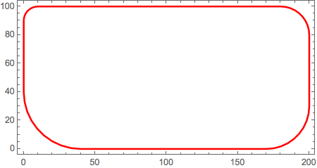
Through[{RegionBounds, Area}[nurcRect]]
{{{0., 200.}, {0., 100.}}, 19344.3}
Notes
NURC = Non-Uniform-Rounded-Corners
To get the more specialized versions nurcRectangle to to looked at first by the kernel during evaluation, the main definition of nurcRectangle which does almost all the error checking and which requires all four corner radii to be explicitly given must appear last in the symbol's down-values list. Therefore, the more specialized versions are defined before the main version in the code. Unfortunately this is not the best order for presentation.
Implementation
Messages
Messages[nurcRectangle] =.
nurcRectangle::badarg = "Argument `1` can not contain `2`";
nurcRectangle::badn = "In argument 4 condition n > 1 is not satisfied";
nurcRectangle::notsat = "Condition `1` is not satisfied";
nurcRectangle::badnrule = "In argument 3 the rule `1` is invalid";
Definitions allowing alternative specifications for argument 3
Give only one numeric radius specification; all corners will use this specification. This is a convenient way to specify a ordinary rounded corner rectangle.
nurcRectangle[{xmin_, ymin_}, {xmax_, ymax_}, r_?NumericQ, n_: 10] :=
  nurcRectangle[{xmin, ymin}, {xmax, ymax}, {r, r, r, r}, n]
Give only one radius specification of the form name -> radius. This is the same as giving the specification: {name -> radius}.
nurcRectangle[{xmin_, ymin_}, {xmax_, ymax_}, rule_Rule, n_: 10] :=
  nurcRectangle[{xmin, ymin}, {xmax, ymax}, {rule}, n]
Give a list containing at least one and at most four radii specifications as rules of the form name -> radius. If two or more rules have the same name token, only the last of these rules will be used. This is only way in which the order of the rules matters.
With[
  {ordering =
     AssociationThread[{"TopLf", "TopRt", "BtmLf", "BtmRt"}, Range[4]]},
  nurcRectangle[
    {xmin_, ymin_}, {xmax_, ymax_}, arg3 : {Repeated[_Rule, 4]}, n_: 10] :=
    Module[{given, names, radii},
      given = Association @@ arg3;
      names = Keys[given];
      If[Check[
           With[{allnames = Keys[ordering]},
             Do[
               If[Not[MemberQ[allnames, nm]],
                 Message[nurcRectangle::badnrule, nm -> given[nm]]],
               {nm, names}]],
           True,
           {nurcRectangle::badnrule}],
        Return[$Failed]];
      radii = ConstantArray[0, 4];
      Set[radii[[#1]], #2] & @@@ ({ordering[#], given[#]} & /@ names);
      nurcRectangle[{xmin, ymin}, {xmax, ymax}, radii, n]]]
Helper functions
There is nothing fancy here. Argument checking is just a matter of slogging through all the constraints placed on the arguments and making sure they are met. If any of the constraints fail to be be met, the function nurcArgChecker issues an error message and returns False; otherwise it returns True.
This is one of those situations where using the seldom used functions,TrueQ and Return, makes sense because their use improves readability of the code.
nurcArgChecker[
  {xmin_, ymin_}, {xmax_, ymax_}, {rtl_, rtr_, rbl_, rbr_}, n_: 10] := (
  If[Not[TrueQ[rtl >= 0]],
    Message[nurcRectangle::badarg, 3, rtl]; Return[False]];
  If[Not[TrueQ[rtr >= 0]],
    Message[nurcRectangle::badarg, 3, rtr]; Return[False]];
  If[Not[TrueQ[rbl >= 0]],
    Message[nurcRectangle::badarg, 3, rbl]; Return[False]];
  If[Not[TrueQ[rbr >= 0]],
    Message[nurcRectangle::badarg, 3, rbr]; Return[False]];
  If[Not[TrueQ[n[[0]] === Integer]],
    Message[nurcRectangle::badarg, 4, n]; Return[False]];
  If[Not[TrueQ[xmin < xmax]],
    Message[nurcRectangle::notsat, "xmin < xmax"]; Return[False]];
  If[Not[TrueQ[ymin < ymax]],
    Message[nurcRectangle::notsat, "ymin < ymax"]; Return[False]];
  If[Not[TrueQ[xmin < xmax]],
    Message[nurcRectangle::notsat, "xmin < xmax"]; Return[False]];
  If[Not[TrueQ[rtl + rtr <= xmax - xmin]],
    Message[nurcRectangle::notsat, "rtl + rtr <= xmax - xmin"]; Return[False]];
  If[Not[TrueQ[rbl + rbr <= xmax - xmin]],
    Message[nurcRectangle::notsat, "rbl + rbr <= xmax - xmin"]; Return[False]];
  If[Not[TrueQ[rtl + rbl <= ymax - ymin]],
    Message[nurcRectangle::notsat, "rtl + rbl <= ymax - ymin"]; Return[False]];
  If[Not[TrueQ[rtr + rbr <= ymax - ymin]],
    Message[nurcRectangle::notsat, "rtr + rbr <= ymax - ymin"]; Return[False]];
  If[Not[TrueQ[n > 1]], Message[nurcRectangle::badn]; Return[False]];
  True)
Given an association describing the corner, nurcCornerPts returns a list of points comprising the points that form the corner in the NURC rectangle.
nurcCornerPts[corner_] :=
  If[corner["r"] == 0,
    {N[corner["xy"]]},
    N[corner["xy"] + {corner["r"] Cos[#], corner["r"] Sin[#]} & /@
      Subdivide[corner["α"], corner["β"], corner["n"]]]]
Main function
This version of nurcRectangle requires its third argument to be a list of four numerical quantities. They must given in the fixed order and satisfy the requirements stated in the section Requirements.
nurcRectangle[
   {xmin_, ymin_}, {xmax_, ymax_}, {rtl_, rtr_, rbl_, rbr_}, n_: 10] /;
    nurcArgChecker[{xmin, ymin}, {xmax, ymax}, {rtl, rtr, rbl, rbr}, n] :=
  Module[{corners},
    corners = {
      (* top right corner *)
      If[rtr == 0,
        <|"xy" -> {xmax, ymax}, "r" -> rtr|>,
        <|"xy" -> {xmax - rtr, ymax - rtr}, "r" -> rtr,
          "α" -> 0, "β" -> π/2, "n" -> n|>],
      (* top-left corner *)
      If[rtl == 0,
        <|"xy" -> {xmin, ymax}, "r" -> rtl|>,
        <|"xy" -> {xmin + rtl, ymax - rtl}, "r" -> rtl,
          "α" -> π/2, "β" -> π, "n" -> n|>],
      (* bottom left corner *)
      If[rbl == 0,
        <|"xy" -> {xmin, ymin}, "r" -> rbl|>,
        <|"xy" -> {xmin + rbl, ymin + rbl}, "r" -> rbl,
          "α" -> π, "β" -> 3 π/2, "n" -> n|>],
      (* bottom right corner *)
      If[rbr == 0,
        <|"xy" -> {xmax, ymin}, "r" -> rbr|>,
        <|"xy" -> {xmax - rbr, ymin + rbr}, "r" -> rbr,
          "α" -> 3 π/2, "β" -> 2 π, "n" -> n|>]};
    Polygon[Catenate[nurcCornerPts /@ corners]]]
Examples of use
Showing that nurcRectangle can reproduce the result of the proof-of-concept computation.
With[
  {rect1 = nurcRectangle[{0, 0}, {200, 100}, {10, 20, 40, 30}, 9],
   rect2 =
     nurcRectangle[
      {0, 0}, {200, 100},
      {"TopRt" -> 20, "BtmRt" -> 30, "TopLf" -> 10, "BtmLf" -> 40}, 9]},
   GraphicsRow[
     Graphics[{EdgeForm[{Thick, Red}], FaceForm[], #}, Frame -> True] & /@
       {rect1, rect2},
     ImageSize -> 500]]

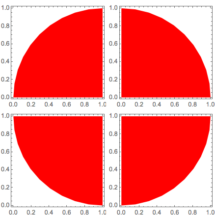
Half-discs and quarter disks.
With[
  {rect1 =
     nurcRectangle[{0, 0}, {2, 1}, {"TopRt" -> 1, "TopLf" -> 1}],
   rect2 =
     nurcRectangle[{0, 0}, {2, 1}, {"BtmLf" -> 1, "BtmRt" -> 1}]},
   GraphicsRow[
     Graphics[
       {EdgeForm[], FaceForm[Red], #},
       Frame -> True,
       ImagePadding -> {{8, 3}, {12, 5}}] & /@ {rect1, rect2},
   Spacings -> -20,
   ImageSize -> 500]]

GraphicsGrid[
  Partition[
    Graphics[
      {EdgeForm[], FaceForm[Red], nurcRectangle[{0, 0}, {1, 1}, # -> 1]},
      Frame -> True,
      ImagePadding -> {{18, 3}, {12, 10}}] & /@
      {"TopLf", "TopRt", "BtmLf", "BtmRt"},
    2],
  Spacings -> 6,
  ImageSize -> 350]
