I am changing initial positions of nodes after the analysis has been initialized (after the SMTAnalysis[...]) and this procedure works fine, but the problem is that change is not shown in postprocessing. How can I get SMTShowMesh to plot modified version of initial configuration?
The following is a small example to illustrate the problem.
<< AceFEM`;
(* A small test analysis with 1 element. *)
Clear[testAnalysis]

testAnalysis[] := (
  SMTInputData[];
  SMTAddDomain["test","OL:SEPEQ1DFHYQ1NeoHooke",{"E *"->1000.,"\[Nu] *"->0.3}];
  SMTAddMesh[{{0,0}, {1,0}, {0,1}, {1,1}},{"test" ->{{1,2,4,3}}}];
  SMTAddEssentialBoundary[{{1, 1 -> 0, 2 -> 0}, {2, 2 -> 0}}];
  SMTAddNaturalBoundary[{4, 2 -> -1}];
  SMTAnalysis[];
  );
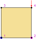
We call the analysis function, see the initial configuration and print initial coordinates of all 4 nodes.
testAnalysis[]
SMTNodeData["X"]
SMTShowMesh[ImageSize->100,"BoundaryConditions"->True,"Marks"->"NodeNumber"]
(*{{0., 0.}, {1., 0.}, {0., 1.}, {1., 1.}}*)
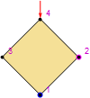
New values of initial coordinates are calculated (rotation of domain for 45 degrees).
newCoordinates = RotationTransform[Pi/4, {0.5, 0.5}] /@ SMTNodeData["X"]
(* {{0.5, -0.207107}, {1.20711, 0.5}, {-0.207107, 0.5}, {0.5, 1.20711}} *)
New coordinates are assigned to nodes and print of coordinates reflects that.
SMTNodeData["X", newCoordinates];
SMTNodeData["X"]
(* {{0.5, -0.207107}, {1.20711, 0.5}, {-0.207107, 0.5}, {0.5, 1.20711}} *)
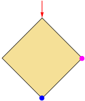
Plotting of mesh does not show the change of initial coordinates. I expect to see element rotated for 45 degrees.
SMTShowMesh[ImageSize->100,"BoundaryConditions"->True,"Marks"->"NodeNumber"]


