15
$\begingroup$

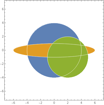
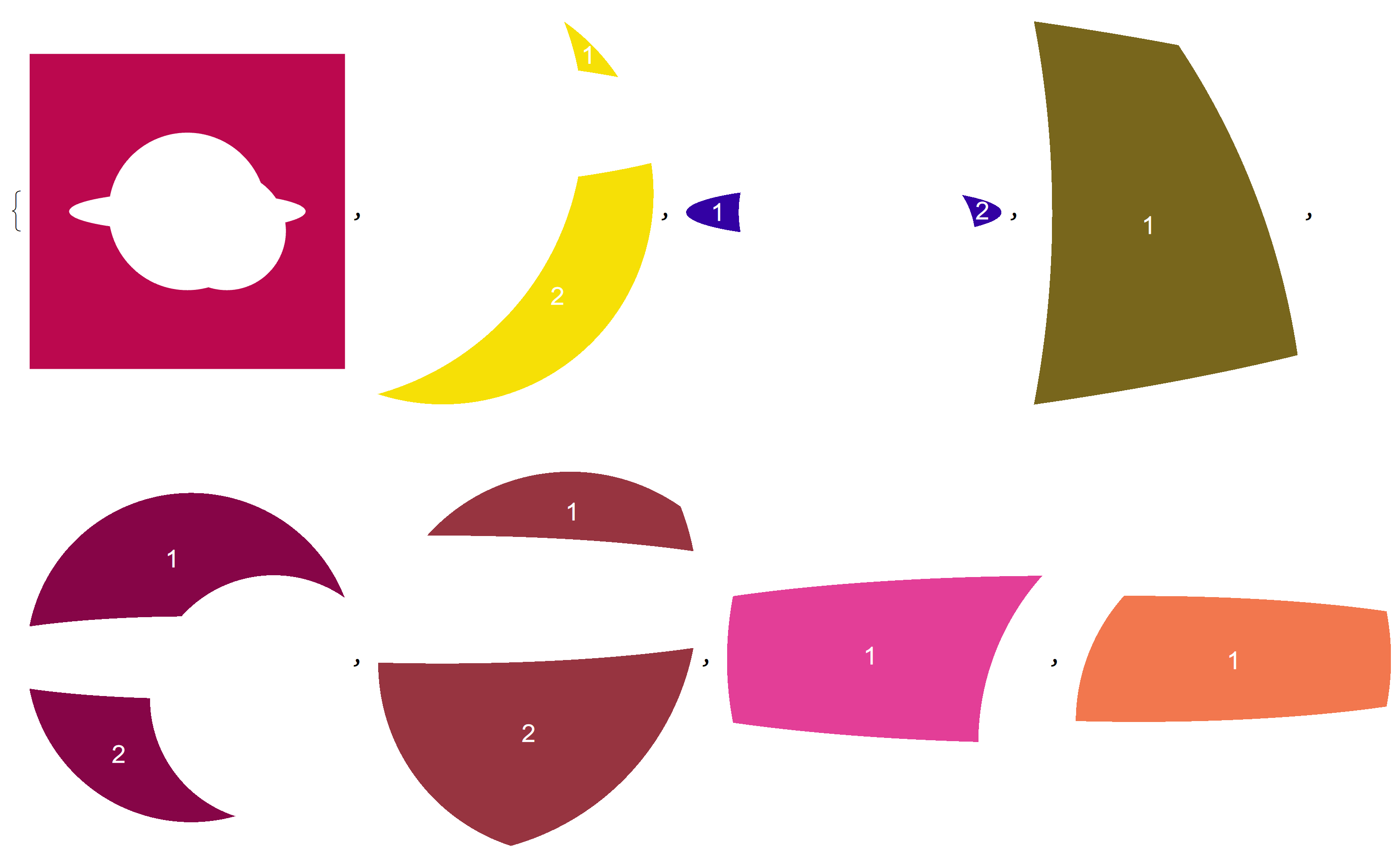
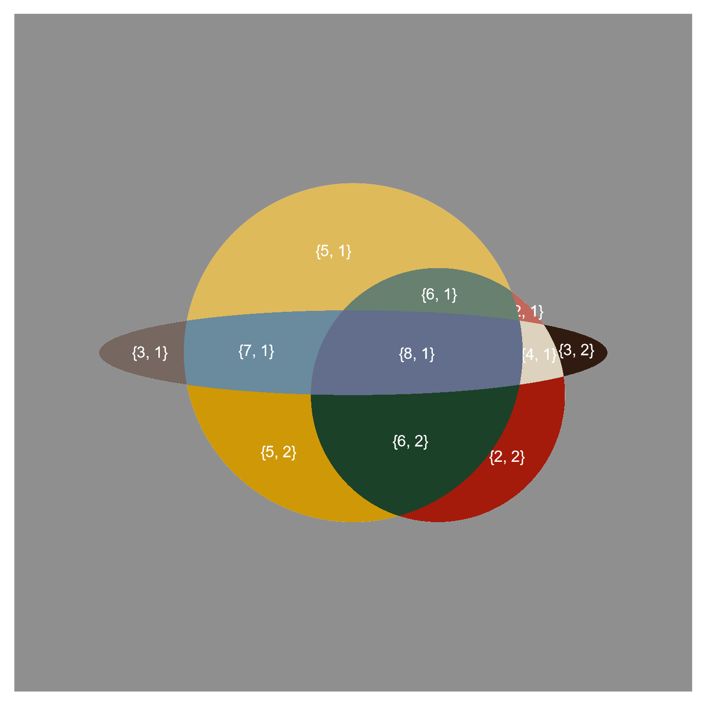
There are three arbitrary curves that defined by three implicit functions. How to separate the 12 regions(one of them is the outside infinite region)

Although we can use image methods to distinguish it, the effect seem not so good. Here we want to get the vector graphics. Thanks!

curves = ContourPlot[{x^2 + y^2 - 16 == 0, 
   x^2/36 + y^2 == 1, (x - 2)^2 + (y + 1)^2 - 9 == 0}, {x, -7, 
   7}, {y, -7, 7}, 
  ContourStyle -> Directive[AbsoluteThickness[2], Black],PlotRangePadding -> None]
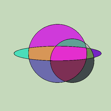
Colorize[MorphologicalComponents[curves]]

enter image description here

Test another way.(I don't know how to extract data from BoundaryMeshRegion directly.)

Clear["Global`*"];
curves = ContourPlot[{x^2 + y^2 - 16 == 0, 
    x^2/36 + y^2 == 1, (x - 2)^2 + (y + 1)^2 - 9 == 0}, {x, -7, 
    7}, {y, -7, 7}, 
   ContourStyle -> Directive[AbsoluteThickness[2], Black], 
   Frame -> False,PlotRangePadding -> None];
Colorize[MorphologicalComponents[curves]];
domains = ImageMesh[curves, Method -> "DualMarchingSquares"];
pts = MeshCoordinates[domains];
lines = MeshCells[domains, "Multicells" -> True][[2]];
regs = BoundaryMeshRegion[pts, #] & /@ lines;
outside = BoundaryMeshRegion[pts, lines[[1]], lines[[2]]];
insides = 
  BoundaryMeshRegion[pts, lines[[#]]] & /@ Range[3, Length[regs]];
Graphics[{Gray, outside, 
  Thread[{ColorData[96] /@ Range[Length[regs] - 2], insides}]}]

enter image description here

$\endgroup$
1
  • 1
    $\begingroup$ This link should help, although this is not a typical Venn Diagram scenario. For instance, the light blue region on the left and the deep blue region on the right are in the same set but are supposed to be colored differently. Instead of A, B, C use ImplicitRegion for each of your equations. $\endgroup$
    – Syed
    Commented Dec 22, 2021 at 7:57

6 Answers 6

7
$\begingroup$

The method by @halmir also work for this case. https://mathematica.stackexchange.com/a/267223/72111

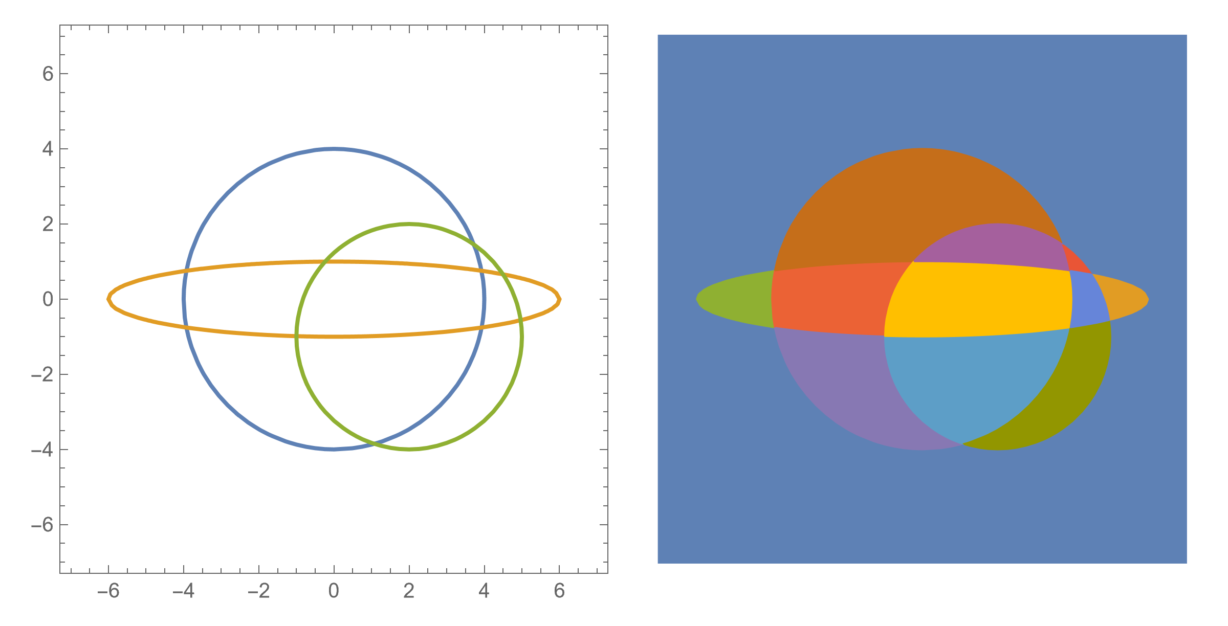
Clear["Global`*"];
eqns = {x^2 + y^2 - 16 == 0, (x - 2)^2 + (y + 1)^2 - 9 == 0, 
   x^2/36 + y^2 == 1};
plot = ContourPlot[eqns // Evaluate, {x, -20, 20}, {y, -20, 20}, 
   MaxRecursion -> 2, PlotPoints -> 50];
lines = Cases[Normal@plot, _Line, -1];
data = Region`Mesh`SplitIntersectingSegments[lines];
pts = data[[1]];
splits = data[[2]];
segments = Flatten[Partition[#, 2, 1] & /@ splits, 1];
g = Graph[Range@Length@pts, UndirectedEdge @@@ segments, 
   VertexCoordinates -> pts];
faces = PlanarFaceList[g];
polys = Polygon[pts[[#]]] & /@ faces;
polys = Delete[polys, First@Ordering[Area@polys, -1]];
colors = ColorData[97] /@ Range@Length@polys;
GraphicsRow[{Graphics[{RandomColor[], #} & /@ lines], 
  Graphics[Thread[{colors, polys}]]}]
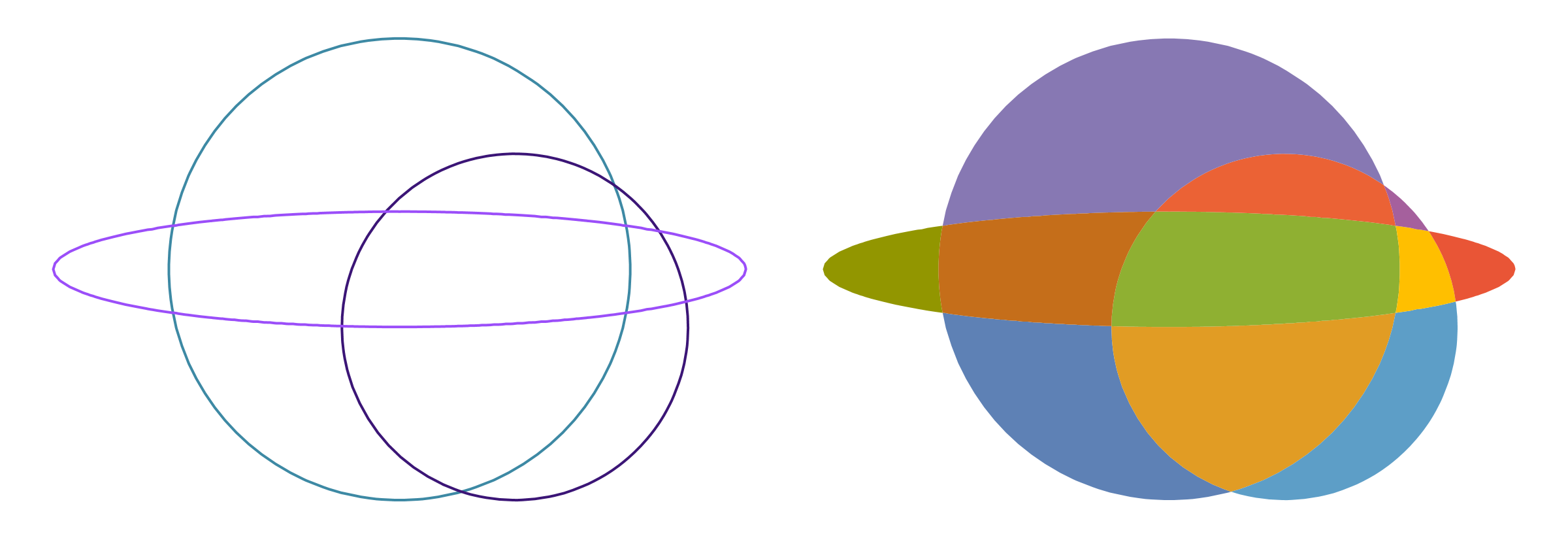
enter image description here

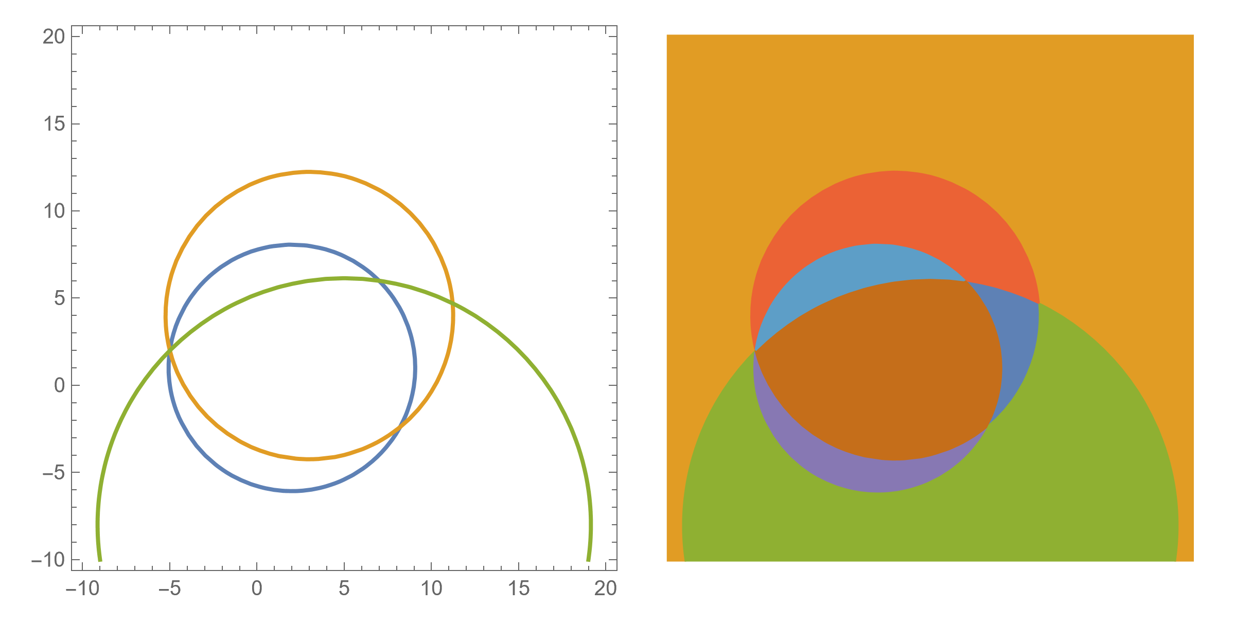
  • Test several arbitrary curves.
Clear["Global`*"];
lines = Table[
   BSplineFunction[RandomReal[1, {10, 2}]] /@ Subdivide[200] // Line, 
   3];
data = Region`Mesh`SplitIntersectingSegments[lines];
pts = data[[1]];
splits = data[[2]];
segments = Flatten[Partition[#, 2, 1] & /@ splits, 1];
g = Graph[Range@Length@pts, UndirectedEdge @@@ segments, 
   VertexCoordinates -> pts];
faces = PlanarFaceList[g];
polys = Polygon[pts[[#]]] & /@ faces;
colors = ColorData[97] /@ Range@Length@polys;
GraphicsRow[{Graphics[{RandomColor[], #} & /@ lines], 
  Graphics[Thread[{colors, polys}]]}]
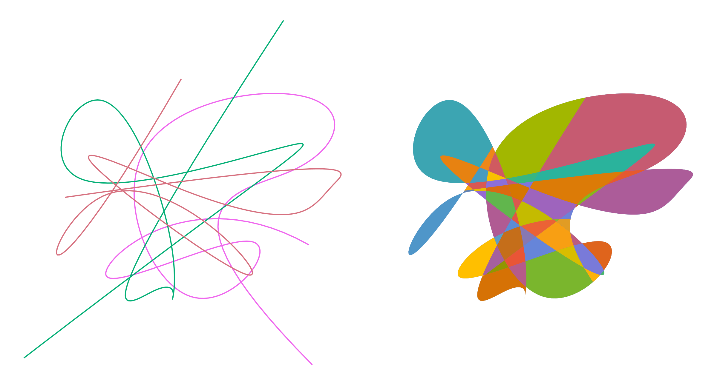
enter image description here

  • We use WindingCount to remove the largest face.
Clear["Global`*"];
eqns = {x^2 + y^2 - 16 == 0, (x - 2)^2 + (y + 1)^2 - 9 == 0, 
   x^2/36 + y^2 == 1};
plot = ContourPlot[eqns // Evaluate, {x, -20, 20}, {y, -20, 20}, 
   MaxRecursion -> 2, PlotPoints -> 50];
lines = Cases[Normal@plot, _Line, -1];
reg = DiscretizeGraphics /@ lines // RegionUnion;
g = Graph[MeshPrimitives[reg, 1] /. Line -> Apply@UndirectedEdge, 
   VertexCoordinates -> MeshCoordinates[reg]];
faces = PlanarFaceList[g];
faces = Select[faces, WindingCount[Line@#, Mean@#] == 1 &];
GraphicsRow[{Graphics@lines, 
  Graphics[{{RandomColor[], Polygon@#} & /@ faces}]}]
  • Add the dual grah.But I don't know why there are multiple edges in the dual planar graph.
Clear["Global`*"];
SeedRandom[123];
eqns = {x^2 + y^2 - 16 == 0, (x - 2)^2 + (y + 1)^2 - 9 == 0, 
   x^2/36 + y^2 == 1};
plot = ContourPlot[eqns // Evaluate, {x, -20, 20}, {y, -20, 20}, 
   MaxRecursion -> 2, PlotPoints -> 50];
lines = Cases[Normal@plot, _Line, -1];
reg = lines // RegionUnion;
g = Graph[MeshPrimitives[reg, 1] /. Line -> Apply@UndirectedEdge, 
   VertexCoordinates -> MeshCoordinates[reg]];
faces = PlanarFaceList[g];
index = FirstPosition[WindingCount[Line@#, Mean@#] & /@ faces, -1];
faces2 = Delete[faces, index // First];
graphics2 = Graphics[{{RandomColor[], Polygon@#} & /@ faces2}];
dual = Graph[VertexList@DualPlanarGraph[g], 
   EdgeList@DualPlanarGraph[g], 
   VertexCoordinates -> RegionCentroid@*Polygon /@ faces, 
   EdgeStyle -> White, VertexStyle -> White, 
   VertexSize -> Automatic];
dual2 = VertexDelete[dual, VertexList[dual][[First@index]]];
Show[graphics2, dual2]
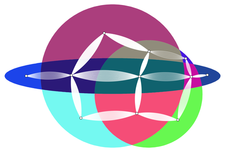
enter image description here

$\endgroup$
2
  • 1
    $\begingroup$ plot = ContourPlot[{x^2 + y^2 - 16 == 0, (x - 2)^2 + (y + 1)^2 - 9 == 0, x^2/36 + y^2 == 1}, {x, -7, 7}, {y, -7, 7}]; pts = Cases[Normal@plot, Line[pts_] :> pts, -1]; poly = WindingPolygon[pts, "EvenOddRule"] maybe another possible way. $\endgroup$
    – cvgmt
    Commented Dec 21, 2023 at 14:17
  • $\begingroup$ reg = MeshRegion[pts, Line@splits]; graph = MeshConnectivityGraph[reg, 0]; faces = PlanarFaceList[graph][[;; , ;; , 2]]; polys = Polygon[pts[[#]]] & /@ faces; polys = Delete[polys, First@Ordering[Area@polys, -1]]; colors = ColorData[97] /@ Range@Length@polys; GraphicsRow[{Graphics[{RandomColor[], #} & /@ lines], Graphics[Thread[{colors, polys}]]}] $\endgroup$
    – cvgmt
    Commented Feb 19 at 2:33
13
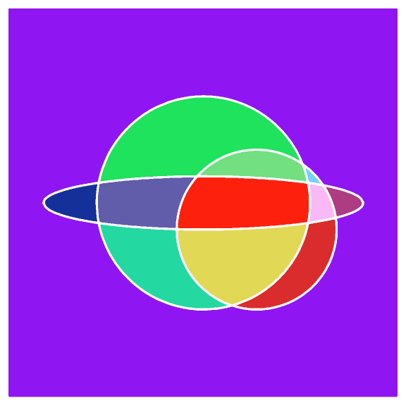
$\begingroup$
eqns = {x^2 + y^2 - 16 == 0, x^2/36 + y^2 == 1, (x - 2)^2 + (y + 1)^2 - 9 == 0};

regions = eqns /. Equal -> LessEqual;

rp = RegionPlot[Evaluate@regions, {x, -7, 7}, {y, -7, 7}, 
    PlotPoints -> 100, PlotStyle -> Opacity[1], 
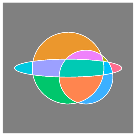
    BoundaryStyle -> Directive[AbsoluteThickness[1], White]]

enter image description here

Use a slightly modified version of separatePolygons from this answer:

ClearAll[separatePolygons]
separatePolygons = Module[
         {imgmesh = 
            ImageMesh @
              ColorNegate @
                Rasterize[Graphics[#[[1]]], ImageResolution -> 200], 
          cb = CoordinateBounds @ #[[1, 1, 1]], cbm}, 
        cbm = CoordinateBounds @ imgmesh;
        MeshPrimitives[imgmesh, 2] /. 
          p_Polygon :> RescalingTransform[cbm, cb] /@ p] &;

Graphics[MapIndexed[{ColorData[97] @ #2[[1]], #} &, 
    separatePolygons[rp]], ImageSize -> Large] 

enter image description here

Note: In versions prior to version 12.0, replace cb = CoordinateBounds @ #[[1, 1, 1]] with cb = CoordinateBounds @ #[[1, 1]].

$\endgroup$
9
$\begingroup$

Using the method in OP's update:

curves = ContourPlot[{x^2 + y^2 - 16 == 0, x^2/36 + y^2 == 1, 
    (x - 2)^2 + (y + 1)^2 - 9 == 0}, {x, -7, 7}, {y, -7, 7}, 
   ContourStyle -> Directive[AbsoluteThickness[2], Black], 
   Frame -> False];

imesh = ImageMesh[curves, Method -> "DualMarchingSquares"];

polygons13 = ReverseSortBy[RegionMeasure] @
  (MeshPrimitives[imesh, 1, Multicells -> True] /. Line -> Polygon @* Apply[Join]);

polygons = Join[{Polygon[# -> #2]& @@ (List @@@ #[[;;2]])}, #[[3;;]]]& @ polygons13;

Graphics[{RandomColor[], #}] & /@ polygons// Multicolumn[#, 3]&

enter image description here

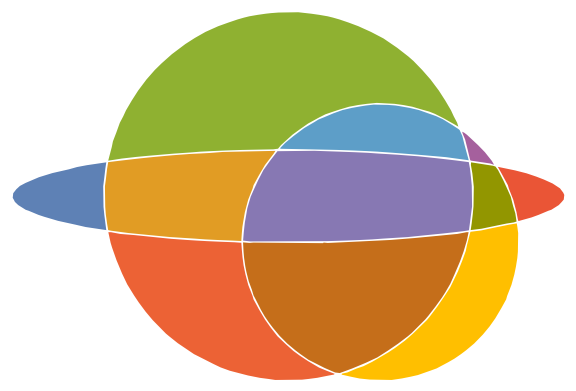
Graphics[{RandomColor[], #} & /@ polygons, ImageSize -> Large]

enter image description here

Note: The first two polygons in polygon13 are the enclosing rectangle and the union of inside polygons:

Graphics[{RandomColor[], #}] & /@ polygons13[[;;2]]

enter image description here

Hence to the need to use the Polygon[# -> #2]& @@ (...) trick to get a polygon with a hole.

$\endgroup$
3
$\begingroup$
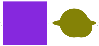
a = {x^2 + y^2 <= 16, x^2/36 + y^2 <= 1, (x - 2)^2 + (y + 1)^2 <= 9};
b = BoundaryDiscretizeRegion@
     BooleanRegion[BooleanFunction[#, Length@a], 
      ImplicitRegion[#, {x, y}] & /@ a] & /@ (2^Range[1, 2^Length@a - 1]);
Graphics[MapIndexed[{ColorData[14]@#2[[1]], #1} &, 
  Flatten[MeshPrimitives[#, 2] & /@ b]]]
$\endgroup$
2
  • $\begingroup$ Wonderful. Could you please add a brief verbal explanation on how you separated these regions? Thanks. $\endgroup$
    – Syed
    Commented Dec 22, 2023 at 15:47
  • $\begingroup$ (+1) Use the BoundaryDiscretizeRegion to seperate the region is a good idea. $\endgroup$
    – cvgmt
    Commented Dec 22, 2023 at 23:45
2
$\begingroup$
  • Another way. Although it is not so elegant. We dilation the lines and use it to separate the plane.
Clear["Global`*"];
plot = ContourPlot[{x^2 + y^2 - 16 == 0, 
    x^2/36 + y^2 == 1, (x - 2)^2 + (y + 1)^2 - 9 == 0}, {x, -7, 
    7}, {y, -7, 7}];
reg = DiscretizeGraphics[plot];
dist = RegionDistance[reg];
ireg = ImplicitRegion[dist@{x, y} >= .01, {{x, -7, 7}, {y, -7, 7}}];
dregs = ConnectedMeshComponents[
   BoundaryDiscretizeRegion[ireg, Method -> "Semialgebraic", 
    MaxCellMeasure -> .01]];
Graphics[
 MapIndexed[{FaceForm[ColorData[97][First@#2]], 
    EdgeForm[ColorData[97][First@#2]], #1} &, dregs]]

enter image description here

  • For another curve.
Clear["Global`*"];
{x0, y0} = {-5, 2}; 
eqns = {(x - 2)^2 + (y - 1)^2 == (x0 - 2)^2 + (y0 - 1)^2, (x - 
       3)^2 + (y - 4)^2 == (x0 - 3)^2 + (y0 - 4)^2, (x - 5)^2 + (y + 
       8)^2 == (x0 - 5)^2 + (y0 + 8)^2};
plot = ContourPlot[eqns // Evaluate, {x, -10, 20}, {y, -10, 20}];
reg = DiscretizeGraphics[plot];
dist = RegionDistance[reg];
ireg = ImplicitRegion[
   dist@{x, y} >= .015, {{x, -10, 20}, {y, -10, 20}}];
dregs = ConnectedMeshComponents[
   BoundaryDiscretizeRegion[ireg, Method -> "Semialgebraic", 
    MaxCellMeasure -> .001]];
Graphics[
 MapIndexed[{FaceForm[ColorData[97][First@#2]], 
    EdgeForm[ColorData[97][First@#2]], #1} &, dregs]]

enter image description here

$\endgroup$
1
$\begingroup$
  • Here only a demonstrate of the ideas of @Karl.
  • At first we spereate the plane by binary decompose method, after that we use ConnectedMeshComponent to seperate the disconneted regions.
ineqs = {x^2 + y^2 <= 16, 
   x^2/36 + y^2 <= 1, (x - 2)^2 + (y + 1)^2 <= 9};
binarydecomposition = 
  Tuples[And@Through /@ {Not, Identity} /@ ineqs];
regs = ImplicitRegion[#, {x, y}] & /@ binarydecomposition;
splits = 
  ConnectedMeshComponents@
     BoundaryDiscretizeRegion[#, {{-8, 8}, {-8, 8}}, 
      MaxCellMeasure -> .01] & /@ regs;
Graphics /@ 
 Table[{RandomColor[], reg, White, 
   MapIndexed[Text[Style[First@#2, 14], RegionCentroid@#1] &, 
    reg]}, {reg, splits}]

enter image description here

Table[{Blend[{White, ColorData[6][i]}, j/Length@splits[[i]]], 
   splits[[i, j]], White, 
   Text[Style[{i, j}, 8], RegionCentroid@splits[[i, j]]]}, {i, 1, 
   Length@splits}, {j, 1, Length@splits[[i]]}] // Graphics

enter image description here

$\endgroup$

Your Answer

By clicking “Post Your Answer”, you agree to our terms of service and acknowledge you have read our privacy policy.

Not the answer you're looking for? Browse other questions tagged or ask your own question.