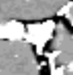
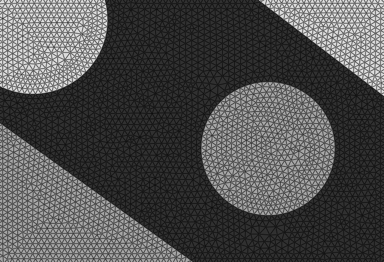
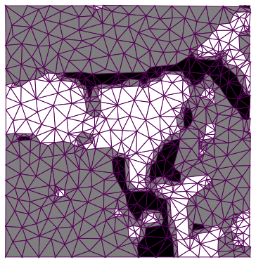
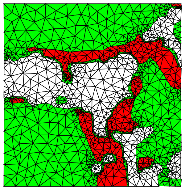
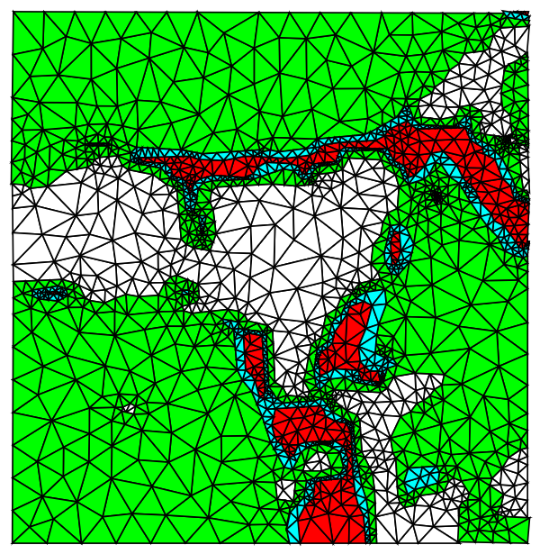
Combining separate meshes from each image component works well for showing the mesh as a graphics. But the combined meshes don't always match at the boundaries between materials and can have tiny gaps. You can see these problems by zooming into the boundary areas in graphics of the combined meshes. They don't matter for visualization, but can be a problem if you want to use the mesh with NDSolve, e.g., solving for heat transfer through materials with different thermal conductivity.
To avoid gaps, it's best to mesh as a single region with internal boundaries between the different materials, as described in the documentation tutorial FEMDocumentation/tutorial/ElementMeshCreation, in the sections "Element Meshes with Subregions" and "Markers".
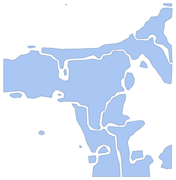
One way to get the boundaries is from the clustering components in Rom38's answer, using the "Contours" property of ComponentMeasurements. Then convert these boundaries into the form required by ToBoundaryMesh:
Needs["NDSolve`FEM`"];

img = Import["https://i.sstatic.net/zD7Ar.jpg"];

Module[{components, boundaries, coords, elements, bmesh,
  pointInEachRegion, reg, parts, markers},

 components = ClusteringComponents[img, 3];

 boundaries =
  Flatten[
   Values@
    ComponentMeasurements[components, "Contours", All,
     "ComponentAssociation"]];

 (* points appearing in the boundaries *)
 coords = Flatten[Cases[boundaries, Line[pts_] :> pts], 1];
 coords = DeleteDuplicates[coords];

 (* replace boundary points by indices into list of coordinates *)
 boundaries =
  boundaries /.
   Line[pts_] :>
    Line[
     pts /.
      p : {_?NumberQ, _?NumberQ} :> FirstPosition[coords, p][[1]]];

 (* remove repeated successive coordinates *)
 boundaries =
  boundaries /.
   Line[pts_] :>
    Line[pts //. {first___, a_, a_, rest___} :> {first, a, rest}];

 (* convert boundary lines into mesh elements *)
 elements =
  boundaries /. Line[pts_List] :> LineElement[Partition[pts, 2, 1]];

 (* mesh with internal boundaries between the materials *)
 bmesh =
  ToBoundaryMesh["Coordinates" -> coords,
   "BoundaryElements" -> elements];

 (* random point in each connected part of each component to specify markers in the mesh *)
 SeedRandom[123];
 pointInEachRegion =
  Table[reg =
    ImageMesh[
     Image[components /. Thread[DeleteCases[Range[3], i] -> 0]]];
   parts = ConnectedMeshComponents[reg];
   RandomPoint /@ parts, {i, 3}];

 (* markers indicating each material, in this case, markers 1, 2 and 3 for the three components *)
 markers =
  Flatten[Table[{#, i} & /@ pointInEachRegion[[i]], {i, 3}], 1];

(* extend boundary mesh to full mesh with markers for each material *)
     ToElementMesh[bmesh, "RegionMarker" -> markers]
 ]
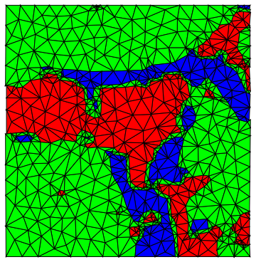
This code creates a single ElementMesh for the whole region, with small mesh elements near the boundary. You can adjust mesh size with options to ToElementMesh.
NDSolve can use this mesh, e.g., to compute heat transport, with material properties, such as thermal conductivity, specified by the value of ElementMarker, which in this case has the values 1, 2 and 3.
Visualize the mesh with colors indicating the marker associated with each mesh triangle:
%["Wireframe"[PlotRangePadding -> None,
  "MeshElementStyle" -> (Directive[FaceForm[#],
       EdgeForm[Opacity[.2]]] & /@ {Lighter@Red, Green, LightBlue})]]
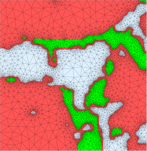
One possible issue with this approach is the boundary between materials returned by ComponentMeasurements is fairly jagged in some places. Smoother boundaries between materials would require a different approach. E.g., use a contour plot of the image data, extract the lines of the contours and then convert them to the form required for ToBoundaryMesh, as done in the above code for boundaries from ComponentMeasurements. This will require more manual adjustment of parameters, e.g., to pick the contours.
p.s., if the image is noisy, you can filter the image first. E.g., with MedianFilter or a filter that preserves edges better, such as BilateralFilter.

