0
$\begingroup$

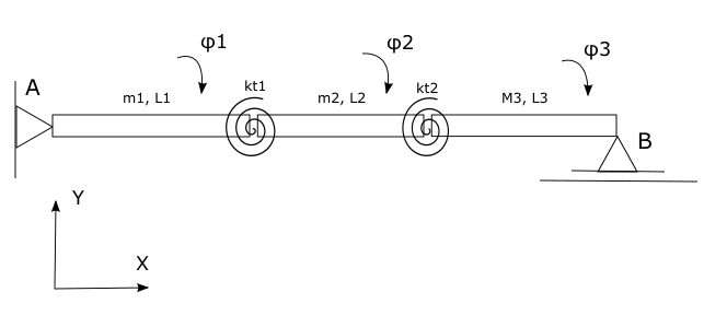
I'm studying mechanical engineering and I have to complete an assignment of animating a 2D graphic of a two degree of freedom system response presented on the picture below. enter image description here I've calculated the response of the system in the code below:
kt1 = 3000(*Nm/rad*);
kt2 = 2000(*Nm/rad*);
L1 = 3(*m*);
L2 = 4(*m*);
L3 = 5(*m*);
m1 = 50(*kg*);
m2 = 70(*kg*);
m3 = 100(*kg*);
g = 9.81(*m/s^2*);

J1 = (m1 L1^2)/3;
Jt2 = (m2 L2^2)/12;
Jt3 = (m3 L3^2)/12;

sol = NDSolve[{J1 (\[Phi]1'')[
      t] == ((4 kt2 L1^2 - 2 kt1 L3) \[Phi]1[t] + 
     2 (2 kt2 L1 (2 + L2) + kt1 L3) \[Phi]2[t] + 
     L1 (L1 (2 Jt3 - 2 L3 m2 + L3^2 m3) (\[Phi]1'')[
          t] + L2 (2 Jt3 - L3 m2 + 
           L3^2 m3) (\[Phi]2'')[t]))/(2 L3),
   Jt2 (\[Phi]2'')[t] == 
    1/(4 L3) ((8 kt2 L1 L2 + 4 kt1 L3 - 2 kt2 L1 L3) \[Phi]1[t] + 
       2 (kt2 (2 + L2) (4 L2 - L3) - 2 kt1 L3) \[Phi]2[t] + 
       L2 (2 L1 (2 Jt3 - L3 m2 + L3^2 m3) (\[Phi]1'')[
            t] + L2 (4 Jt3 - L3 m2 + 
             2 L3^2 m3) (\[Phi]2'')[t])),
   \[Phi]1[0] == 0.1, \[Phi]2[0] == 0.2, \[Phi]1'[0] == 
    0.5, \[Phi]2'[0] == 0},
  {\[Phi]1[t], \[Phi]1'[t], \[Phi]1''[t], \[Phi]2[t], \[Phi]2'[
    t], \[Phi]2''[t]},
  {t, 0, 500, 0.001}, Method -> "ExplicitRungeKutta", 
  MaxSteps -> Infinity]

I'm interested in x-y motion so naturally I first have to convert the coordinates:

Yt2 = L1 \[Phi]1''[t] + (L2 \[Phi]2''[t])/2;
Yt3 = (L3 \[Phi]3''[t] )/2;
\[Phi]3[t] = -((L1 \[Phi]1[t] + L2 \[Phi]2[t])/2);
\[Phi]3''[t] = -((L1 \[Phi]1''[t] + L2 \[Phi]2''[t])/2);

This is where my problem occurs as I have little experience in animating 2D motion. The animation can be minimalistic without the torsion springs included. So id just need two support as shown in the picture and 3 beams that I would assign functions of motion to. My question is if such an animation of the system in the picture is possible in mathematica. And if possible how would i go about making such an animation(which function to use, are there any tutorials out there).

Edit: I fixed a typo and replaced graphic of the model with a more accurate graphic that shows angular displacements and coordinate system.

$\endgroup$
4
  • $\begingroup$ Welcome to Mathematica.SE! I hope you will become a regular contributor. To get started, 1) take the introductory tour now, 2) when you see good questions and answers, vote them up by clicking the gray triangles, because the credibility of the system is based on the reputation gained by users sharing their knowledge, 3) remember to accept the answer, if any, that solves your problem, by clicking the checkmark sign, and 4) give help too, by answering questions in your areas of expertise. $\endgroup$
    – bbgodfrey
    Commented Jul 1, 2021 at 12:46
  • $\begingroup$ Can you please show on your diagram how exactly are the coordinate system and the angles (φ1, φ2 and φ3) defined? $\endgroup$
    – Domen
    Commented Jul 1, 2021 at 14:02
  • $\begingroup$ Also, take a look at this simple example of Animate. Animate[Show[Graphics[{ Line[{{0, 0}, {1, .5 Sin[t]}, {2, 0}}], Line[{{-.1, -1}, {-.1, 1}}], Triangle[{{-.1, -.1}, {-.1, .1}, {0, 0}}] }]], {t, 0, 10}] $\endgroup$
    – Domen
    Commented Jul 1, 2021 at 14:12
  • $\begingroup$ You have a typo: ([Phi]2^'') $\endgroup$ Commented Jul 1, 2021 at 14:16

1 Answer 1

2
$\begingroup$

I have corrected your definition of $\varphi_3$, so that the final end of the third beam is constrained to horizontal movement.

\[Phi]3[t_] := ArcSin[-((L1 Sin[\[Phi]1[t]] + L2 Sin[\[Phi]2[t]])/L3)];
X0 = 0;
Y0 = 0;

X1 = L1 Cos[\[Phi]1[t]];
Y1 = L1 Sin[\[Phi]1[t]];
X2 = X1 + L2 Cos[\[Phi]2[t]];
Y2 = Y1 + L2 Sin[\[Phi]2[t]];
X3 = X2 + (L3 Cos[\[Phi]3[t]]);
Y3 = Y2 + (L3 Sin[\[Phi]3[t]]);


Animate[Evaluate@Show[Graphics[{
      Line[{{0, 0}, {X1, Y1}, {X2, Y2}, {X3, Y3}}],
      Line[{{-1, -4}, {-1, 4}}],
      Line[{{9, -1}, {15, -1}}],
      Disk[{X1, Y1}, .1], Disk[{X2, Y2}, .1],
      EdgeForm[Black], White,
      Triangle[{{-1, -1}, {-1, 1}, {0, 0}}],
      Triangle[{{X3 - 1, -1}, {X3, 0}, {X3 + 1, -1}}]
      }] /. (sol // First), PlotRange -> {{-2, 15}, {-2, 2}}], {t, 0, 
  10}, AnimationRate -> .5]

Animation

$\endgroup$
13
  • $\begingroup$ thank you this solution is very helpful. Would it also be possible to add a roller support on the right side that allows motion in X dimension olny? $\endgroup$ Commented Jul 1, 2021 at 15:57
  • $\begingroup$ Sure, but can you just write down first how the $x$ and $y$ coordinates of the joints are expressed by the angles $\varphi$? $\endgroup$
    – Domen
    Commented Jul 1, 2021 at 16:09
  • $\begingroup$ These are the coordinates in XY expressed with angles. They are placed where the torsion springs are. [X1(Kt1)=L1*Cos(φ1), Y1Kt1)=L1*Sin(φ1), X2(Kt2)=L1*Cos(φ1)+L2*Cos(φ2), Y2Kt1)=L1*Sin(φ1)+L2*Sin(φ2)]. $\endgroup$ Commented Jul 1, 2021 at 16:17
  • $\begingroup$ This is the same way as I have defined the coordinates in my attempt. But as you can see, the right end of the third beam also has some vertical ($y$) movement. According to your drawing, this should not be happening, because it is constrained to horizontal movement. So, there is probably a mistake somewhere, either in the differential equations or in the definition of coordinates ... $\endgroup$
    – Domen
    Commented Jul 1, 2021 at 16:35
  • $\begingroup$ The rotation of second and the third beam is revolving around the centre of mass of each beam so the coordinates change to X2 = X1 + (L2 Cos[[Phi]2[t]])/2; X3 = X2 + (L3 Cos[[Phi]3[t]])/2. This is likely the coordinate problem as im fairly certain the DE's are correct. $\endgroup$ Commented Jul 1, 2021 at 16:45

Your Answer

By clicking “Post Your Answer”, you agree to our terms of service and acknowledge you have read our privacy policy.

Not the answer you're looking for? Browse other questions tagged or ask your own question.