33
$\begingroup$

I have the following code that generates a finite element mesh:

Needs["NDSolve`FEM`"]       
order = 2;
mesh = ToElementMesh[
DiscretizeGraphics[
GraphicsComplex[{{0, 4}, {5, 4}, {5, 0}, {8, 0}, {8, 8}, {0, 8}}, 
Polygon[{1, 2, 3, 4, 5, 6}]]], "MeshElementType" -> QuadElement, 
"MeshOrder" -> order, "NodeReordering" -> True]
mesh["Wireframe"]

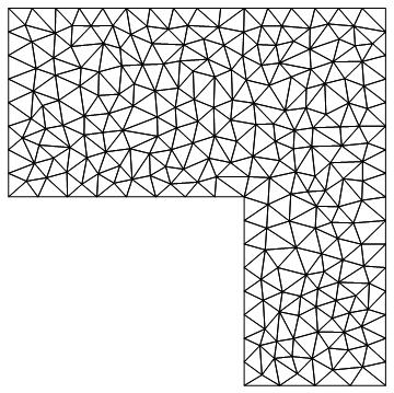
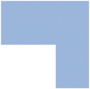
I'm indicating that the element type i want is a quadrilateral type ("MeshElementType" -> QuadElement), but it still creates a mesh of triangles. Can i change this?

Related paper: https://onlinelibrary.wiley.com/doi/full/10.1002/cae.21958

enter image description here

$\endgroup$
3
  • $\begingroup$ it would be easy to hand code for such simple geometry. $\endgroup$
    – george2079
    Commented Feb 10, 2017 at 14:16
  • $\begingroup$ @george2079 i need a very fine mesh. For simplicity i have chosen to shown a coarse mesh in this question. It is very dificult to create more than 1000 nodes by hand. $\endgroup$
    – Stratus
    Commented Feb 10, 2017 at 14:22
  • $\begingroup$ i did not literally mean by hand, you would use a loop of course. The density doesn't matter, but the exact shape of the boundary does. $\endgroup$
    – george2079
    Commented Feb 10, 2017 at 14:49

7 Answers 7

21
$\begingroup$

Based on the tutorial here

QuadElement meshes behave exactly the same as TriangleElement meshes, with the exception that, for linear quad elements, four incidents per element are needed, and, for quadratic elements, eight incidents per element are needed.

here is another possible answer:

Needs["NDSolve`FEM`"]

rectangleA = {{0, 4}, {8, 8}};
rectangleB = {{5, 0}, {8, 4}};

pitch = 0.25;

rectAx = 1/pitch (rectangleA[[2, 1]] - rectangleA[[1, 1]]) + 1;
rectAy = 1/pitch (rectangleA[[2, 2]] - rectangleA[[1, 2]]) + 1;
rectBx = 1/pitch (rectangleB[[2, 1]] - rectangleB[[1, 1]]) + 1;
rectBy = 1/pitch (rectangleB[[2, 2]] - rectangleB[[1, 2]]) + 1;

coordinatesA = 
  Flatten[Table[{x, y}, {x, rectangleA[[1, 1]], rectangleA[[2, 1]], pitch},
   {y, rectangleA[[1, 2]], rectangleA[[2, 2]], pitch}], 1];
coordinatesB = 
  Flatten[Table[{x, y}, {x, rectangleB[[1, 1]], rectangleB[[2, 1]], pitch},
   {y, rectangleB[[1, 2]], rectangleB[[2, 2]], pitch}], 1];

coordinates = Join[coordinatesA, coordinatesB];

incidents = Join[
   Flatten[
    Table[{j*rectAy + i, j*rectAy + i + 1, (j - 1)*rectAy + i + 1, (j - 1)*rectAy + i},
     {i, 1, rectAy - 1}, 
     {j, 1, rectAx - 1}], 1],
   Flatten[
    Table[{j*rectBy + i, j*rectBy + i + 1, (j - 1)*rectBy + i + 1, (j - 1)*rectBy + i},
     {i, 1 + Length[coordinatesA], Length[coordinatesA] + rectBy - 1},
     {j, 1, rectBx - 1}], 1]
   ];

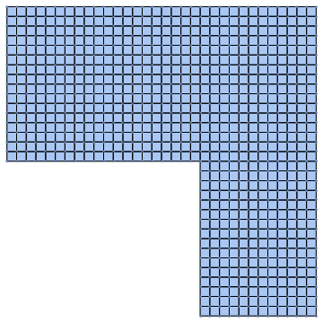
mesh1 = ToElementMesh["Coordinates" -> coordinates, 
   "MeshElements" -> {QuadElement[incidents]}, 
   "NodeReordering" -> True];
mesh2 = MeshOrderAlteration[mesh1, 2];
mesh2["MeshOrder"]

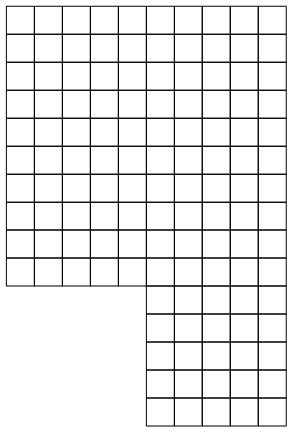
enter image description here

Show[
 DiscretizeGraphics[
  GraphicsComplex[{{0, 4}, {5, 4}, {5, 0}, {8, 0}, {8, 8}, {0, 8}}, 
   Polygon[{1, 2, 3, 4, 5, 6}]]],
 mesh2["Wireframe"],
 ListPlot[coordinates]
 ]

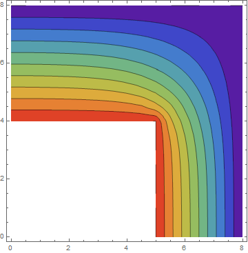
Sample Problem:

sol = NDSolveValue[{D[u[x, y], x, x] + D[u[x, y], y, y] == 0,
   DirichletCondition[u[x, y] == 100, y == 4 && x <= 5 || y <= 4 && x == 5],
   DirichletCondition[u[x, y] == 0, y == 8 || x == 8]},
  u, {x, y} ∈ mesh2]

sol["ElementMesh"]
ContourPlot[sol[x, y], {x, y} ∈ mesh2, Mesh -> None, 
 ColorFunction -> "Rainbow", PlotRange -> All, 
 PlotLegends -> Automatic]

enter image description here

$\endgroup$
18
$\begingroup$

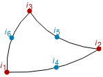
Here is a different approach. The idea is to first generate a second order triangle mesh. Next a center coordinate is added in every triangle. Then we split every triangle into three first order quads making use of the newly added center coordinate and the initial second order triangle incidents.
enter image description here

So we add a node in the center of the element and create the quad elements {c,6,1,4}, {c,4,2,5} and {c,5,3,6}.

Start with an initial triangle mesh:

Needs["NDSolve`FEM`"]
m = ToElementMesh[
   DiscretizeGraphics[
    GraphicsComplex[{{0, 4}, {5, 4}, {5, 0}, {8, 0}, {8, 8}, {0, 8}}, 
     Polygon[{1, 2, 3, 4, 5, 6}]]]];

Two helper functions that work for second order triangle mesh elements. If one want to extend this to 3D then you'd need to add a tetToHex function.

getMidEleCoords = Compile[{{eleCoords, _Real, 2}},
   Mean[eleCoords], RuntimeAttributes -> {Listable}];

triToQuad = Compile[{{triInci, _Integer, 1}, {midInci, _Integer, 0}}, {
    {midInci, triInci[[6]], triInci[[1]], triInci[[4]]},
    {midInci, triInci[[4]], triInci[[2]], triInci[[5]]},
    {midInci, triInci[[5]], triInci[[3]], triInci[[6]]}
    }
   , RuntimeAttributes -> {Listable}
   ];

getConverterCode[TriangleElement] := triToQuad;
getNumOfResEle[TriangleElement] := 3
getConvertedEleType[TriangleElement] := QuadElement

First, we compute the new coords within the triangle/tet elements:

coords = m["Coordinates"];
numOfCoords = Length[coords];
meshEle = m["MeshElements"];
inci = ElementIncidents[meshEle];
markers = ElementMarkers[meshEle];
eleCoords = GetElementCoordinates[coords, #] & /@ inci;
midEleCoords = getMidEleCoords[eleCoords];
numOfMidCoords = Length /@ midEleCoords;
temp = Join[{numOfCoords}, numOfMidCoords];
temp = FoldList[Plus, temp] + 1;
midEleInci = MapThread[Range, {Most[temp], Rest[temp - 1]}];
newCoords = Join[coords, Join @@ midEleCoords];
(*Max[midEleInci]===Length[newCoords]*)

The we generate the new elements:

newEle = Table[
   Block[{thisMeshEle, thisType, thisInci, thisMarker, converter, 
     newEle, newEleMarkers},
    thisMeshEle = meshEle[[i]];
    thisType = Head[thisMeshEle];
    thisInci = ElementIncidents[thisMeshEle];
    thisMarker = ElementMarkers[thisMeshEle];
    converter = getConverterCode[thisType];
    newEle = Join @@ converter[thisInci, midEleInci[[i]]];
    newEleMarkers = 
     Join @@ Transpose[
       ConstantArray[thisMarker, getNumOfResEle[thisType]]];
    getConvertedEleType[thisType][newEle, newEleMarkers]
    ]
   , {i, Length[meshEle]}];

Generate a quad mesh:

mq1 = ToElementMesh["Coordinates" -> newCoords, 
  "MeshElements" -> newEle]
(* ElementMesh[{{0., 8.}, {0., 8.}}, {QuadElement["<" 1338 ">"]}] *)

Look at the mesh:

mq1["Wireframe"]
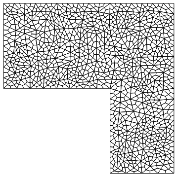
enter image description here

This is now a first order mesh:

mq1["MeshOrder"]
1

One can use MeshOrderAlteration[mq1, 2] to then subsequently generate a second order mesh.

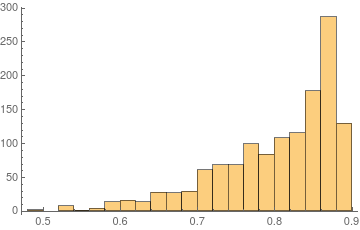
Histogram[Join @@ mq1["Quality"]]
enter image description here

Quality looks OK, but a smoothing of some kind (e.g. Laplacian smoothing) might be well worth trying out.

(Update: There is a follow up question that discusses the idea of Laplacian smoothing. Spoiler: Does not look like it's worth the trouble)

Solve a model problem over the mesh:

sol = NDSolveValue[{-Laplacian[u[x, y], {x, y}] == 1, 
    DirichletCondition[u[x, y] == 0, True]}, u, {x, y} \[Element] mq1];
Plot3D[sol[x, y], {x, y} \[Element] sol["ElementMesh"]]

enter image description here

Since this will generate three quad elements for every triangle the mesh cell measure is lower than what it needs to be, one could adjust for that by making use of "MaxCellMeasure" in the initial triangle mesh.

Hope this helps.

$\endgroup$
16
$\begingroup$

That's not possible in general in V11.0. The only primitive from which a quad mesh can be generated is

ToElementMesh[Rectangle[]]

or

ToElementMesh[FullRegion[2], {{0, 1}, {0, 1}}]

So to get a quad mesh for a more complicated shape you'd need to program a bit and use

ToElementMesh["Coordinates"->..., "MeshElements"->{QuadElement[....]}]

As another approach you could merge 2 triangles to a quad and thus get a mostly quad mesh. If you do that. I'd be interested in seeing the result.

Here is another piece of information: If you have a first order mesh you can make that second order.

m = ToElementMesh["Coordinates" -> coordinates, 
   "MeshElements" -> {QuadElement[incidents]}];
m["MeshOrder"]
1

m2 = MeshOrderAlteration[m, 2];
m2["MeshOrder"]
2

Since your case does not involve curved boundaries no mid side nodes (second order nodes) need to be moved to the proper position.

$\endgroup$
6
  • $\begingroup$ don't even try merging triangles, you will end up with horribly unacceptable shape elements. $\endgroup$
    – george2079
    Commented Feb 10, 2017 at 14:57
  • 2
    $\begingroup$ @george2079, probably not easy, but it has been done $\endgroup$
    – user21
    Commented Feb 10, 2017 at 15:22
  • $\begingroup$ Are quad elements constrained to single order? $\endgroup$
    – Young
    Commented Feb 10, 2017 at 17:30
  • $\begingroup$ @Young, no. They can be quadratic. $\endgroup$
    – user21
    Commented Feb 10, 2017 at 17:46
  • 2
    $\begingroup$ @Young, see update on getting a second order mesh. $\endgroup$
    – user21
    Commented Feb 10, 2017 at 18:00
16
$\begingroup$

this is a bit of a hack but it works for this example:

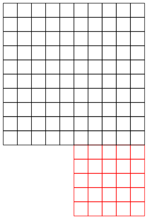
generate separate rectangle meshes -- note the connected edge nodes must be exactly coincident.

<< NDSolve`FEM`
m1 = ToElementMesh[Rectangle[{-10, 0}, {0, 10}], 
   "MeshElementType" -> QuadElement, MaxCellMeasure -> 4, 
   "MeshOrder" -> 1];
m2 = ToElementMesh[Rectangle[{-20, 10}, {0, 30}], 
   "MeshElementType" -> QuadElement, MaxCellMeasure -> 4, 
   "MeshOrder" -> 1];
Show[{m1["Wireframe"] /. EdgeForm[GrayLevel[0]] -> EdgeForm[Red], 
  m2["Wireframe"]}]

all of this works fine for "MeshOrder"->2 btw

enter image description here

join the node lists and shift the second mesh to the new list index:

allnodes = Join[m1["Coordinates"], m2["Coordinates"]];
common = Intersection[m1["Coordinates"], m2["Coordinates"]];
m2el = Map[Length@m1["Coordinates"] + # &, m2["MeshElements"] , {2}];

now point the duplicate nodes in the second mesh to the nodes in the first mesh:

m2el = m2el /. ((Rule @@ Reverse@Flatten[Position[allnodes, #]]) & /@ 
     common);

Edit: This step is not needed for NDSolve NDsolve evidently merges coincident nodes (beware other solvers might not do that).

create a new mesh:

allelements = Join[m1["MeshElements"], m2el];
ToElementMesh["Coordinates" -> allnodes, 
  "MeshElements" -> allelements];
Show[%["Wireframe"]]

enter image description here

Note we left stray unconnected nodes in the allnodes list, I don't think that should be a problem ..

Edit: test problem: ( with MaxCellMeasure -> 1/4 )

eqns = {
   Laplacian[u[x, y], {x, y}] == 0,
    DirichletCondition[u[x, y] == 1, y == 30], 
   DirichletCondition[u[x, y] == 0, y == 0]};
uif = NDSolveValue[eqns, u, {x, y} \[Element] mesh]
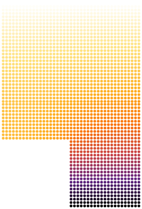
Graphics[MapThread[{ColorData["SunsetColors"][#2], PointSize[.02], 
    Point[#1]} &,
  {uif["Grid"], uif["ValuesOnGrid"]}]] 

enter image description here

a better way to plot..

vertvals = ColorData["SunsetColors"]@Extract[uif["ValuesOnGrid"], 
       First@Position[   uif["Grid"] , #] ] & /@ allnodes; 
(* note the "Grid" list and `allnodes` are not the same because of the unused nodes in `allnodes` *)
Graphics[GraphicsComplex[ allnodes,
  Cases[ allelements , {n1_, n2_, n3_, n4_,___} :> 
    Polygon[{n1, n2, n3, n4}], Infinity], VertexColors -> vertvals ]]

enter image description here

$\endgroup$
16
+100
$\begingroup$

Edit:

This method is now implemented as StructuredMesh function (2D and 3D) in FEMAddOns package. With minor enhancements it is also implemented in MeshTools package.


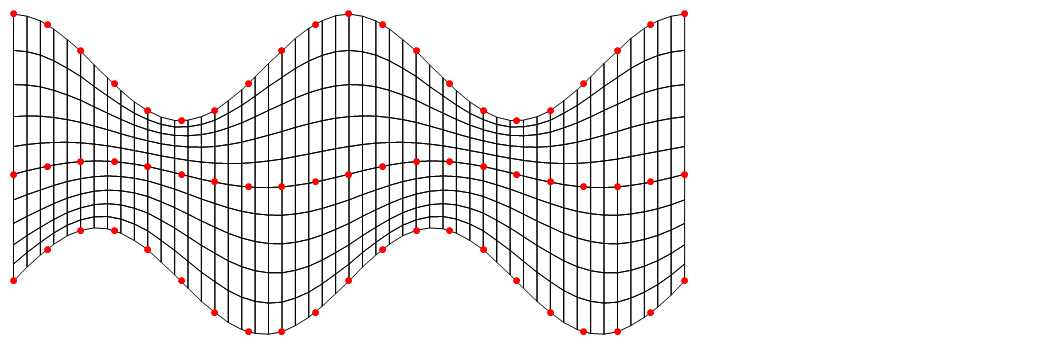
If the shape of geometric region can be somehow described as a rectangular array of points then structured quadrilateral mesh can be generated on it. I hope the next example will more clearly illustrate my point.

First we create a raster of 2D points and then pass it to structuredMesh function which uses 2D interpolation of each coordinate. It returns ElementMesh object according to specified number of elements in each direction.

 raster = With[{end = 4 Pi, n = 20},
   N@{
     Table[{x, Sin[x] - 2}, {x, 0, end, end/n}],
     Table[{x, Sin[x]/4}, {x, 0, end, end/n}],
     Table[{x, Cos[x] + 2}, {x, 0, end, end/n}]
     }
   ];

mesh = structuredMesh[raster, {50, 10}, InterpolationOrder -> 2];
Show[
 mesh["Wireframe"],
 Graphics[{Red, PointSize[0.01], Point[Flatten[raster, 1]]}]
 ]

mesh_1

Definition of structuredMesh and helper function(s) is given below.

getElementConnectivity[nx_,ny_]:=Flatten[
    Table[
        {(i-1)*(nx+1)+j,i*(nx+1)+j,i*(nx+1)+j+1,(i-1)*(nx+1)+j+1},
        {i,1,ny},
        {j,1,nx}
    ],
    1
]


structuredMesh::array="Raster of input points must be full array of numbers with depth of 3.";

structuredMesh//Options={InterpolationOrder->1};
structuredMesh[raster_,{nx_,ny_},opts:OptionsPattern[]]:=Module[
    {order,dim,restructured,xInt,yInt,zInt,nodes,connectivity},
    If[Not@ArrayQ[raster,3,NumericQ],Message[structuredMesh::array];Return[$Failed]];

    order=OptionValue[InterpolationOrder]/.Automatic->1;
    dim=Last@Dimensions[raster];

    restructured=Transpose[raster,{2,3,1}];
    xInt=ListInterpolation[restructured[[1]],{{0,1},{0,1}},InterpolationOrder->order];
    yInt=ListInterpolation[restructured[[2]],{{0,1},{0,1}},InterpolationOrder->order];

    nodes=Flatten[#,1]&@If[dim==3,
        zInt=ListInterpolation[restructured[[3]],{{0,1},{0,1}},InterpolationOrder->order];
        Table[{xInt[i,j],yInt[i,j],zInt[i,j]},{i,0,1,1./ny},{j,0,1,1./nx}]
        ,
        Table[{xInt[i,j],yInt[i,j]},{i,0,1,1./ny},{j,0,1,1./nx}]
    ];

    connectivity=Reverse/@getElementConnectivity[nx,ny];

    If[dim==3,
        ToBoundaryMesh["Coordinates"->nodes,"BoundaryElements"->{QuadElement[connectivity]}],
        ToElementMesh["Coordinates"->nodes,"MeshElements"->{QuadElement[connectivity]}]
    ]
]

And this is how the function can be used for OP's shape. In general the more complicated shapes can be manually split to "topological quadrialterals", meshed separately with structured meshes and then merged in one mesh.

raster2 = {{{5, 0}, {8, 0}}, {{5, 4}, {8, 8}}, {{0, 4}, {0, 8}}};
mesh = structuredMesh[raster2, 10*{1, 2}];
mesh["Wireframe"]

mesh_2

$\endgroup$
1
  • 2
    $\begingroup$ This is a very cool way to do it. $\endgroup$
    – user21
    Commented Feb 26, 2018 at 10:04
10
$\begingroup$

Edit:

This method is now also implemented as ToQuadMesh function in FEMAddOns package and as TriangleToQuadMesh in MeshTools package.


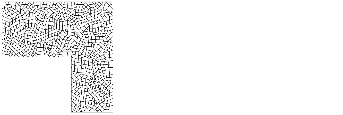
Once the open source package is downloaded and installed generating a quad element mesh then works like this:

Needs["FEMAddOns`"]
triMesh = 
  ToElementMesh[
   DiscretizeGraphics[
    GraphicsComplex[{{0, 4}, {5, 4}, {5, 0}, {8, 0}, {8, 8}, {0, 8}}, 
     Polygon[{1, 2, 3, 4, 5, 6}]]]];

mesh = ToQuadMesh[triMesh];
mesh["Wireframe"]

quad mesh

Note that this also returns a second order mesh:

mesh["MeshOrder"]
2

AceFEM package contains a useful function SMTTriangularToQuad which converts triangular mesh to quadrilaterals. It works only for 1st order mesh.

<< AceFEM`
triMesh = ToElementMesh[
  DiscretizeGraphics[
    GraphicsComplex[{{0,4},{5,4},{5,0},{8,0},{8,8},{0,8}},Polygon[{1,2,3,4,5,6}]]], 
  "MeshOrder" -> 1
]

mesh = SMTTriangularToQuad[triMesh];
mesh["Wireframe"]

quad mesh

$\endgroup$
1
  • $\begingroup$ ToQuadMesh is probably the most general method of the solutions presented for this question. $\endgroup$
    – user21
    Commented Jun 18, 2018 at 15:06
9
$\begingroup$

For integer valued coordinates like you have here, you can make a grid of rational step size and use RegionMember + ArrayMesh.

Something like:

mr = MeshRegion[{{0, 4}, {5, 4}, {5, 0}, {8, 0}, {8, 8}, {0, 8}}, Polygon[{1, 2, 3, 4, 5, 6}]];

{{x1, x2}, {y1, y2}} = bds = RegionBounds[mr];

δ = 1/10;
xrng = Range[x1, x2 - δ, δ];

onoff = Boole[Table[
  RegionMember[mr, Thread[{xrng, y}]],
  {y, y1, y2 - δ, δ}
]];

quad = ArrayMesh[onoff, DataRange -> bds, DataReversed -> True]

enter image description here

MeshCellCount[quad]
{4561, 8960, 4400}
$\endgroup$

Your Answer

By clicking “Post Your Answer”, you agree to our terms of service and acknowledge you have read our privacy policy.

Not the answer you're looking for? Browse other questions tagged or ask your own question.