So I'm building this software that designs mechanisms to follow a specific curve. I'm inspired by the work done by Disney https://youtu.be/DfznnKUwywQ?t=38s
Here's what I've done so far:
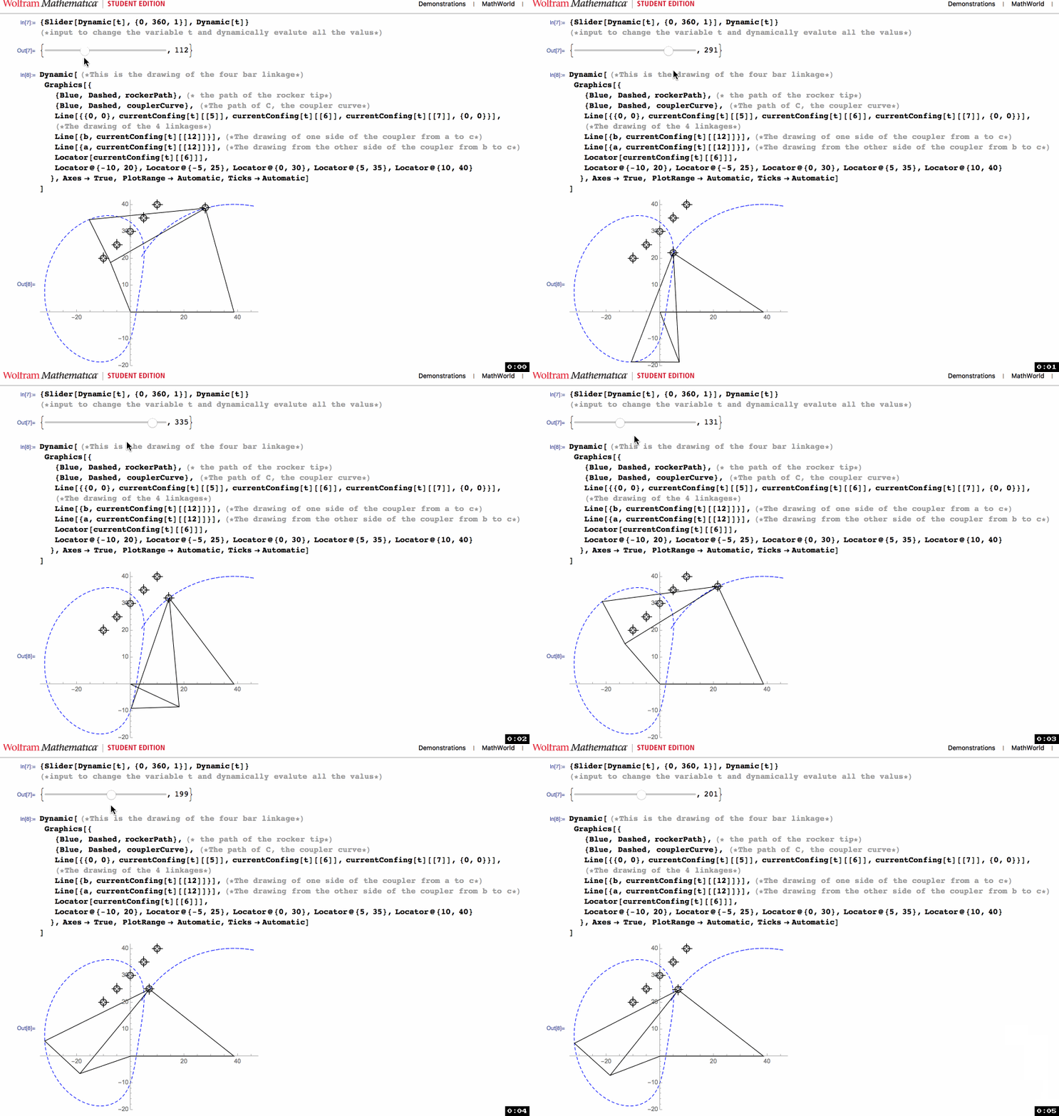
- I've done the modelling of the mechanism and tracing the curve resulting from the specific dimensions:

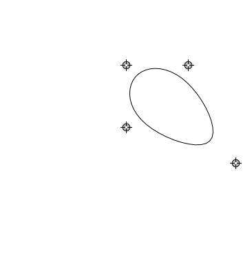
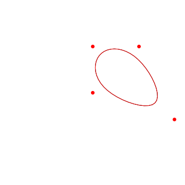
- I've tried to write my own implementation of genetic algorithm to optimize the error between 6 points {x,y} on the curve and 6 design points but I'm getting really bad results.
My Question:
- Is it possible to take input from the user by drawing a curve like the Disney software allows the user to?
- If it's possible, What kind of optimization can I use? The drawn curve is a list of 360 {x,y} points.
Here's my code if you want to give it a try:
crankRockerSolver[rcx_, rcy_, r1_, r4_, r3_, r2_] = (*
  r1 is the crank; r2 is the coupler; r3 is the rocker;
  r4 is the link between oA and oB;
  This is a pure function that returns expressions with an empty slot \
in the place of the input angle which is passed to it later;
  This function calculates the output angle of the rocker.*)
  {a1 =
     N[Sin[# Degree]],
    b1 = N[r4/r1 - Cos[# Degree]],
    c1 = N[-r4/r3 Cos[# Degree] +
       N[(r1^2 - r2^2 + r3^2 + r4^2)/(2 r1 r2)]],
    \[Psi] =
     180 - ( 2 ArcTan[
          N[(a1 + \[Sqrt](a1^2 + b1^2 - c1^2))/(b1 + c1)]]/
         Degree),(*Output Angle Calculated by Equation from the \
refrence*)

    a = N[AngleVector[{r1, # Degree}]],(*point A Starting from origin*)

        b = N[
      AngleVector[{r4,
        0}, {r3, \[Psi]  Degree}]],(*Point B Starting from Ob*)

    ob = N[AngleVector[{r4, 0}]],(*Point oB*) (*#7*)
    v = b - a,(*this is the vector of the coupler link.
    The coupler link closes the triangle between a2 and b2.
    mathematica deals with vectors are geometrical vectors from the \
origin. in order to get the vector from a to b,
    the vectors a2 and b2 has to be included in one equation to be \
solved namely a2+coupler=b2*)

    Subscript[\[Theta],
     3] = (VectorAngle[{1, 0}, v]/
       Degree),(*this is the Subscript[\[Theta], 3]
    angle from the diagram. The angle between the coupler and x-axis*)

        Subscript[c, x] =
     N[r1 Cos[# Degree] + rcx Cos[Subscript[\[Theta], 3] Degree] -
       rcy Sin[Subscript[\[Theta], 3] Degree]],
    Subscript[c, y] =
     N[r1 Sin[# Degree] + rcx Sin[Subscript[\[Theta], 3] Degree] +
       rcy Cos[Subscript[\[Theta], 3] Degree]],
    c = {Subscript[c, x], Subscript[c,
      y]} (*C is the coupler floating link. This co-
    ordinates of this point is to be calculated from the two \
equations above. The equations come form the refrences.*)
    } &;

currentConfing =
  crankRockerSolver[11.424901483235672`, 15.082872962462773`,
   21.718791706141616`, 35.80178707917261`, 36.90228323939509`,
   38.91747403096488];

rockerPath =
  Line@Table[
    currentConfing[t][[6]], {t, 0, 360,
     1}];(*This using Table function to get an array of the \
coordinates of one point, rocker tip, at different values of \
currentConfig function then draw a line from it in graphics*)

couplerCurve =
  Line@Table[
    currentConfing[t][[12]], {t, 0, 360,
     1}];(*Same concept yet this traces the cooupler curve*)

{Slider[Dynamic[t], {0, 360, 1}], Dynamic[t]}

Dynamic[ (*This is the drawing of the four bar linkage*)
 Graphics[{
   {Blue, Dashed, rockerPath},(*
   the path of the rocker tip*)
   {Blue, Dashed,
    couplerCurve}, (*The path of C, the coupler curve*)

   Line[{{0, 0}, currentConfing[t][[5]], currentConfing[t][[6]],
     currentConfing[t][[7]], {0, 0}}],(*The drawing of the 4 linkages*)

      Line[{b,
     currentConfing[t][[
      12]]}],(*The drawing of one side of the coupler from a to c*)

    Line[{a,
     currentConfing[t][[
      12]]}],(*The drawing from the other side of the coupler from b \
to c*)
   Locator[currentConfing[t][[6]]],
   Locator@{0.9206, 6.37}, Locator@{0.605, 6.29},
   Locator@{0.427, 6.23}, Locator@{0.163, 6.11},
   Locator@{-0.0501, 5.988}, Locator@{-0.256, 5.84},
   }, Axes -> True, PlotRange -> Automatic, Ticks -> Automatic]
 ]


