Here are three points in space.
SeedRandom[2];
 {p1, p2, p3} = {{x1, y1, z1}, {x2, y2, z2}, {x3, y3, z3}} =
   RandomReal[{-3, 3}, {3, 3}];
If the center is $p=(x,y,z)$ and the radius is $r$, then the distance from $p$ to each $p_i$ must be exactly $r$. Thus, for each $i=1,2,3$, we have
$$(x - x_i)^2 + (y - y_i)^2 + (z - z_i)^2 = r^2.$$
Furthermore, the point $p$ must lie on the plane determined by $p_1$, $p_2$, and $p_3$. If $\vec{n}$ is a vector normal to that plane, then an equation for the plane is
$$\vec{n}\cdot(p-p_1)=0.$$
That gives us four equations in the four unknowns $x$, $y$, $z$, and $r$. Using the fact that $\vec{v}_1 \times \vec{v}_2$ is always perpendicular to $\vec{v}_1$ and $\vec{v}_2$, we can set up this system of equations as follows:
v1 = p2 - p1;
v2 = p3 - p1;
{v1, v2} = Orthogonalize[{v1, v2}];
n = Cross[v1, v2];
eqs = {
   (x - x1)^2 + (y - y1)^2 + (z - z1)^2 == r^2,
   (x - x2)^2 + (y - y2)^2 + (z - z2)^2 == r^2,
   (x - x3)^2 + (y - y3)^2 + (z - z3)^2 == r^2,
   n.({x, y, z} - p1) == 0
};
Strictly speaking, the Orthogonalize step is not necessary, but it will be convenient a bit later.
Here is the solution of the system. We want the positive $r$ value, of course.
solution = NSolve[eqs, {x, y, z, r}]

(* Out:
 {{x -> -0.333316, y -> -0.850768, z -> 0.653921, r -> 2.38624},
  {x -> -0.333316, y -> -0.850768, z -> 0.653921, r -> -2.38624}}
*)
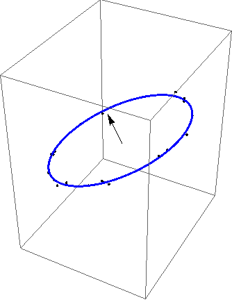
We now have enough information to parametrize the circle and plot it together with the points, so we can see how this all looks. Note that in the Mathematica code, I'm using {x0,y0,z0} to denote the center and r0 to denote the radius. Also, this depends on the fact that v1 and v2 are perpendicular unit vectors, which is one reason we used the Orthogonalize command.
{x0, y0, z0} = {x, y, z} /. First[solution];
r0 = r /. First[solution];
Show[{
  ParametricPlot3D[{x0, y0, z0} + r0*v1*Cos[t] + r0*v2*Sin[t], {t, 0, 2 Pi}],
  Graphics3D[{PointSize[Large], Point[{p1, p2, p3}]}]
  }]
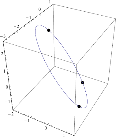
The tight integration of symbolics and graphics is one of the great strengths of Mathematica and this example shows why it's so nice - it's super simple to see that we've done things correctly!
Now, in order to check if your six points all lie on the same circle, we just need a way to check if any particular point lies on that circle. Thus, suppose we have another point that we suspect must lie on this circle, say:
{x4, y4, z4} = {x0, y0, z0} + r0*v1*Cos[t] + r0*v2*Sin[t] /.
  t -> RandomReal[{0, 2 Pi}];
It's distance to {x0,y0,z0} should be r0, so the following should be zero:
Chop[(x4 - x0)^2 + (y4 - y0)^2 + (z4 - z0)^2 - r0^2]

(* Out: 0 *)
and it should also lie on the plane:
Chop[n.({x4, y4, z4} - p1)]

(* Out: 0 *)
Mapping to a plane
I don't really see a major advantage to working in a plane, but it can certainly be done. Consider the following $3\times3$ matrix $M$ defined using column vectors $\vec{v}_1$, $\vec{v}_2$, and $\vec{v}_3$:
$$
M = \left(
\begin{array}{ccc}
\vec{v}_1 & \vec{v}_2 & \vec{v}_3
\end{array}
\right).
$$
If ${\mathbb R}^3$ has the standard unit basis vectors $\vec{e}_1$, $\vec{e}_2$, and $\vec{e}_3$, then direct computation shows that
$$M \, \vec{e}_i = \vec{v}_i.$$
As a result, $M^{-1}$ does the opposite:
$$M^{-1} \, \vec{v}_i = \vec{e}_i.$$
In particular, if we take $\vec{v}_1$ and $\vec{v}_2$ to be the vectors defined above and then set the third vector to be our normal vector, $\vec{v}_3 = \vec{n}$, then $M^{-1}$ should map our three original points to some horizontal plane.
This is an absolutely standard trick in linear algebra that helps us understand the basics behind changes of bases. It's also a second point where it is nice that v1 and v2 are perpendicular, unit vectors, for this implies that $M$ and $M^{-1}$ are orthogonal matrices and, therefore, preserve the shape of the original configuration. Without this assumption, $M$ could be a shear transformation so the image of the points under $M^{-1}$ wouldn't necessarily lie on a circle, though they would lie on a plane.
Let's try it - I'm using rr to denote the original matrix $M$ (I'm thinking of it as being rotation, which it almost might be) and I'm using RR to denote the inverse.
rr = Transpose[{v1, v2, n}];
RR = Inverse[rr];
RR.# & /@ {p1, p2, p3}

(* Out: {
         {-2.46374, -1.07249, -0.282502},
         {0.770168, -1.07249, -0.282502},
         {0.729536, 2.47387, -0.282502}
        }
*)
After application of the matrix RR, all the points have the same $z$ value. We could simply map Most onto this result if we want 2D points.


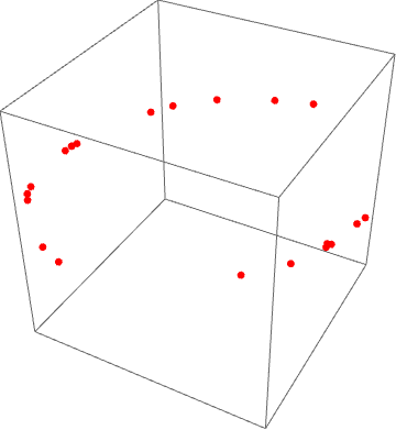
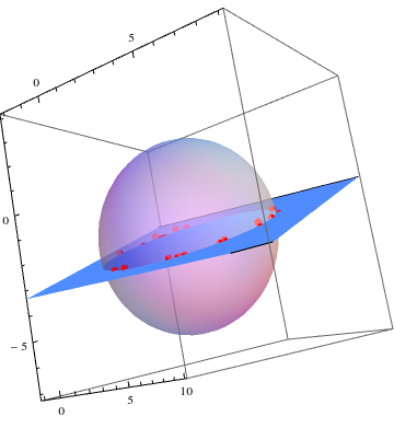
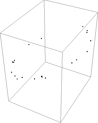
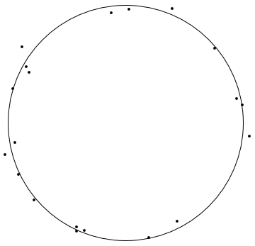


Orthogonalizecan be your friend here. First average the points (that is, compute their centroid) and subtract it to make all coordinates relative to the centroid. ApplyingOrthogonalizeto the matrix of coordinates should produce just two nonzero orthogonal basis vectors. (If not, your points are not coplanar.) Rewrite each shifted point as a linear combination of those basis vectors: the coefficients are your new coordinates. Details are given at mathematica.stackexchange.com/questions/10333 (and its comments: J.M. provided some useful pointers). $\endgroup$