12
$\begingroup$

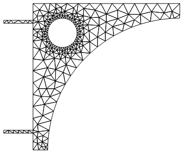
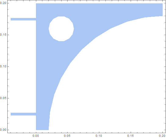
I am trying to make a finite element mesh in 2D. The features are not found by ToElementMesh. This is a shelf bracket with nails. I build the region using RegionDifference and RegionUnion and the result is clear.

   Needs["NDSolve`FEM`"]
L = 0.2; (* Bracket side length *)
d = 0.02;  (* End edge lenght *)
r = L - d;   (* radius of curved edge *)
r1 = d;    (* radius of hole *)
L2 = 0.004; (* nail thickness *)
L3 = 0.04; (* nail length *)
L4 = L/8; (* location of nail from bottom *)
Y = 10^3;  (* modulus of elasticity *)
ν = 33/100;  (* Poisson ratio *)

reg = RegionDifference[
   RegionUnion[
    Rectangle[{0, 0}, {L, L}],
    Rectangle[{-L3, L4 - L2/2}, {0, L4 + L2/2}],
    Rectangle[{-L3, (L - L4) - L2/2}, {0, (L - L4) + L2/2}]
    ],
   RegionUnion[
    Disk[{L, 0}, r],
    Disk[{2 d, L - 2 d}, r1]]
   ];
Show[Region[reg], PlotRange -> All, Frame -> True]
Mathematica graphics

This region looks good. Now I try to mesh.

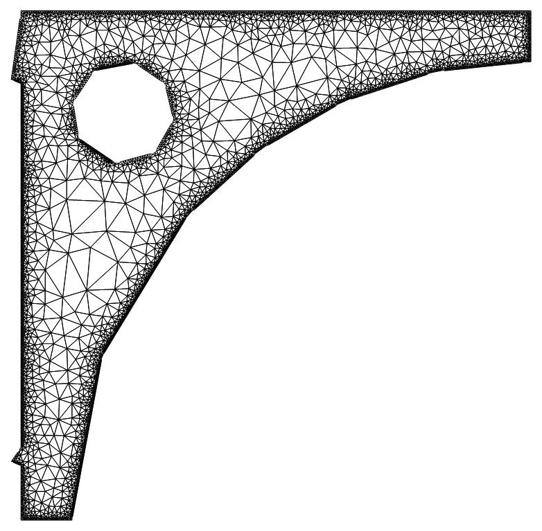
mesh = ToElementMesh[reg, "BoundaryMeshGenerator" -> "Continuation", 
   "MaxBoundaryCellMeasure" -> 0.001, "MaxCellMeasure" -> 0.0001];
Show[mesh["Wireframe"], PlotRange -> All]
Mathematica graphics

The nails have been lost and the edges are very poorly represented. I have tried different options for ToElementMesh but have not hit on one that works. What is happening? Version 11.1 for Windows. Thanks

Edit

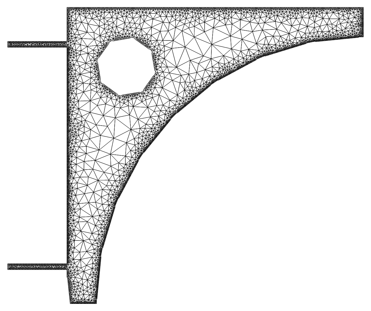
Helpful user21 gave a solution below which works for the resolution in his example. I have tried to increase the resolution and this is what happens.

mesh = ToElementMesh[reg, {{-0.04`, 0.2`}, {0.`, 0.2`}}, 
   "MaxBoundaryCellMeasure" -> 0.001, 
   "BoundaryMeshGenerator" -> {"RegionPlot", "SamplePoints" -> 200} ];
Show[mesh["Wireframe"], PlotRange -> All]
Mathematica graphics

The curved boundaries and the lower part of the vertical straight boundary are badly formed. I would like a high resolution because when doing stress calculations gradients of the solution are needed. Any more thoughts?

Combining the suggestions from the answers below is successful.

Further edit

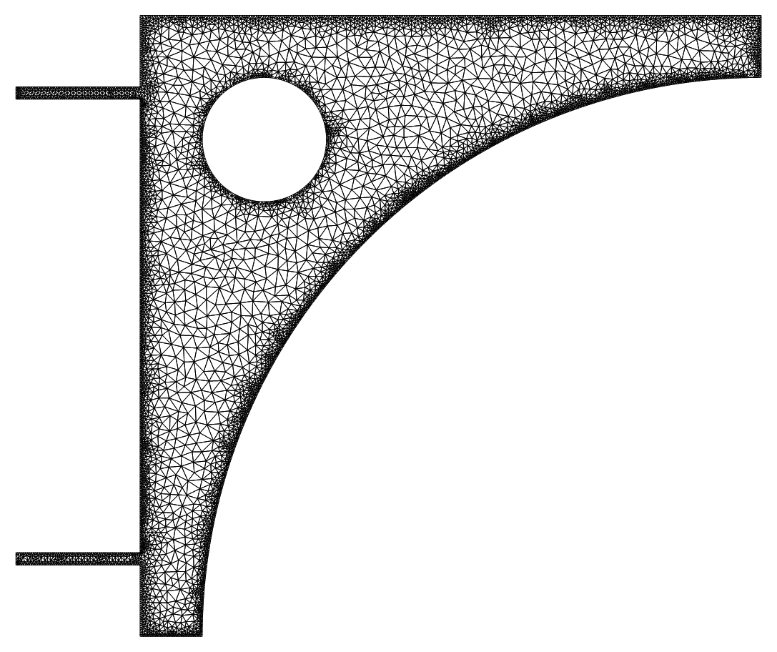
If you use this mesh you will need to use the workaround from this question. Add the option "ImproveBoundaryPosition" -> False to ToElementMesh. The mesh coordinates are not all contained within the solution interpolation function. So the final ToElementMesh expression was

mesh = ToElementMesh[reg, {{-L3, L}, {0, L}}, 
   "MaxBoundaryCellMeasure" -> 0.001, MaxCellMeasure -> 1.1*^-6, 
   AccuracyGoal -> 8, MeshQualityGoal -> 1, 
   "BoundaryMeshGenerator" -> {"RegionPlot", "SamplePoints" -> 200},
   "ImproveBoundaryPosition" -> False];

and it worked to give this mesh
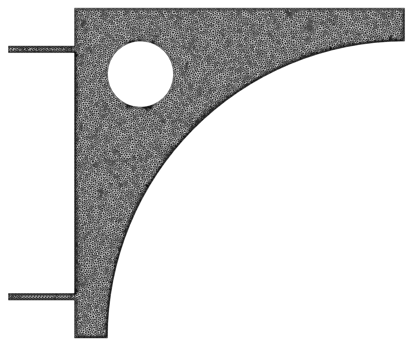
Mathematica graphics

$\endgroup$
3
  • $\begingroup$ I am a bit skeptical about the "ImproveBoundaryPosition" -> False option. The geometry in this question does not show these sharp corners like the one in the linked question. When you plot(?) over the interpolating function do you use the mesh or the region reg? $\endgroup$
    – user21
    Commented Sep 21, 2017 at 5:34
  • $\begingroup$ @user21 The error does not occur when plotting but when the coordinates of the grid are put into the solution interpolation function to get the values. Shall I make a new question? $\endgroup$
    – Hugh
    Commented Sep 21, 2017 at 8:26
  • $\begingroup$ Yes, please if you do not mind. Let's see what's going on. As a side note, I may not be able to look at it right way though but I will. $\endgroup$
    – user21
    Commented Sep 21, 2017 at 8:33

2 Answers 2

9
$\begingroup$

I've had success using AccuracyGoal -> 8 for meshing regions with small dimensions. (Note: Use fractions for greater accuracy)

Needs["NDSolve`FEM`"]
L = 2/10;  (*Bracket side length*)
d = 2/100; (*End edge lenght*)
r = L - d; (*radius of curved edge*)
r1 = d;    (*radius of hole*)
L2 = 4/1000; (*nail thickness*)
L3 = 4/100;  (*nail length*)
L4 = L/8;    (*location of nail from bottom*)
Y = 10^3;    (*modulus of elasticity*)
ν = 33/100;  (*Poisson ratio*)

reg = 
 RegionDifference[
  RegionUnion[Rectangle[{0, 0}, {L, L}], 
  Rectangle[{-L3, L4 - L2/2}, {0, L4 + L2/2}], 
  Rectangle[{-L3, (L - L4) - L2/2}, {0, (L - L4) + L2/2}]], 
  RegionUnion[Disk[{L, 0}, r], Disk[{2 d, L - 2 d}, r1]]];
Show[Region[reg], PlotRange -> All, Frame -> True]

mesh = ToElementMesh[reg, {{-4/100, 2/10}, {0, 2/10}}, 
   "MaxBoundaryCellMeasure" -> 0.001, MaxCellMeasure -> 1*^-5, 
    AccuracyGoal -> 7, MeshQualityGoal -> 1,
   "BoundaryMeshGenerator" -> {"RegionPlot", "SamplePoints" -> 50}];
Show[mesh["Wireframe"], PlotRange -> All]

enter image description here

$\endgroup$
7
  • $\begingroup$ In what version have you tried this? $\endgroup$
    – user21
    Commented Sep 20, 2017 at 15:23
  • $\begingroup$ Version 11.1 and 11.2 $\endgroup$
    – Young
    Commented Sep 20, 2017 at 15:24
  • $\begingroup$ In version 11.1 it fails to find the nails. The curved edges are good though. $\endgroup$
    – Hugh
    Commented Sep 20, 2017 at 15:25
  • $\begingroup$ With accuracy goal and with "BoundaryMeshGenerator" -> {"RegionPlot", "SamplePoints" -> 200 as you have just added seems to work. Can anyone give guidance on what the AccuracyGoal number and the SamplePoints number actually refer to? $\endgroup$
    – Hugh
    Commented Sep 20, 2017 at 15:31
  • 2
    $\begingroup$ I get it to work too now, it must have been a skew setting. Thanks. (+1) $\endgroup$
    – user21
    Commented Sep 20, 2017 at 16:23
15
$\begingroup$

These should work:

Method 1

ToElementMesh[reg,{{-0.04`, 0.2`}, {0.`, 0.2`}},
"MaxBoundaryCellMeasure" -> 0.005, 
  "BoundaryMeshGenerator" -> {"RegionPlot", 
    "SamplePoints" -> 41}]["Wireframe"]

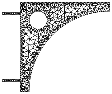
mesh

The problem is that "Coninuation" fails (which needs to be investigated) and the "RegionPlot" one does need the "SamplePoints" (think "PlotPloints"). Hope this helps.

If you need a finer mesh you can use:

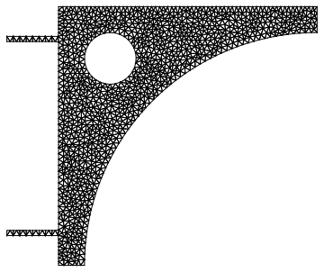
ToElementMesh[reg, {{-0.04`, 0.2`}, {0.`, 0.2`}}, 
  "MaxBoundaryCellMeasure" -> 0.005, "MaxCellMeasure" -> 0.00001, 
  "BoundaryMeshGenerator" -> {"RegionPlot", 
    "SamplePoints" -> 41}]["Wireframe"]

enter image description here

Method 2

Here is a better way to do it:

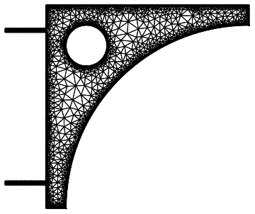
mesh = ToElementMesh[reg, RegionBounds[reg], 
   "BoundaryMeshGenerator" -> {"BoundaryDiscretizeRegion"}, 
   "MaxBoundaryCellMeasure" -> 0.001, "MaxCellMeasure" -> 0.0001];
mesh["Wireframe"]

enter image description here

All of these methods are documented in ToBoundaryMesh. There you can find more info.

Method 3

Here is yet another way to do it, but that will requite version 11.2:

 L = 1./5; d = 1./50; r = L - d; r1 = d; L2 = 1./250; L3 = 1./25; L4 = 
 L/8;
reg = RegionDifference[
   RegionUnion[Rectangle[{0, 0}, {L, L}], 
    Rectangle[{-L3, L4 - L2/2}, {0, L4 + L2/2}], 
    Rectangle[{-L3, (L - L4) - L2/2}, {0, (L - L4) + L2/2}]], 
   RegionUnion[Disk[{L, 0}, r], Disk[{2 d, L - 2 d}, r1]]];

Now we make boundary discretizations of the components and construct the region from those:

bdr = BoundaryDiscretizeRegion /@ reg[[2]];
bmr = Fold[RegionDifference, bdr]

enter image description here

Next, we create a NumericalRegion and attach the boundary mesh to it:

Needs["NDSolve`FEM`"]
nr = ToNumericalRegion[reg, RegionBounds[reg]];
bmesh = ToBoundaryMesh[bmr];
SetNumericalRegionElementMesh[nr, bmesh];

When we now mesh that numerical region have both the symbolic and the boundary representation available and a good approximation can be generated:

mesh = ToElementMesh[nr];
mesh["Wireframe"]

To compare the area of the mesh with the area of the symbolic representation we use:

narea = Total[mesh["MeshElementMeasure"], 2];

and

L = 1/5; d = 1/50; r = L - d; r1 = d; L2 = 1/250; L3 = 1/25; L4 = 
 L/8;
reg2 = RegionDifference[
   RegionUnion[Rectangle[{0, 0}, {L, L}], 
    Rectangle[{-L3, L4 - L2/2}, {0, L4 + L2/2}], 
    Rectangle[{-L3, (L - L4) - L2/2}, {0, (L - L4) + L2/2}]], 
   RegionUnion[Disk[{L, 0}, r], Disk[{2 d, L - 2 d}, r1]]];
sarea = Integrate[1, {x, y} \[Element] reg2];

The result:

narea - sarea
-2.4810104379269227`*^-7

I think this is quite good.

enter image description here

$\endgroup$
8
  • $\begingroup$ Thanks for your suggestion. It works for large resolutions but fails for small resolutions. I have added an edit to my original question to show the problem with this approach. Any ideas? $\endgroup$
    – Hugh
    Commented Sep 20, 2017 at 14:01
  • $\begingroup$ @Hugh, what do you mean with 'small resolutions' ? Do you mean small mesh cell size? $\endgroup$
    – user21
    Commented Sep 20, 2017 at 15:17
  • $\begingroup$ Yes I mean small mesh cell size. $\endgroup$
    – Hugh
    Commented Sep 20, 2017 at 15:21
  • $\begingroup$ I would appreciate if downvoters leave a small message so that I can respond to the issue. $\endgroup$
    – user21
    Commented Sep 20, 2017 at 15:24
  • 1
    $\begingroup$ Thanks to both you and @Young. Can you give me more information on good values to use for AccuracyGoal and SamplePoints $\endgroup$
    – Hugh
    Commented Sep 20, 2017 at 16:28

Your Answer

By clicking “Post Your Answer”, you agree to our terms of service and acknowledge you have read our privacy policy.

Not the answer you're looking for? Browse other questions tagged or ask your own question.