Here is an alternate approach using a graded mesh.
Define some helper functions for a graded mesh
Here are some functions that I've used to create 1d to 3D anisotropic meshes. Not all functions are used.
(*Import required FEM package*)
Needs["NDSolve`FEM`"];
(* Define Some Helper Functions For Structured Meshes*)
pointsToMesh[data_] :=
  MeshRegion[Transpose[{data}],
   Line@Table[{i, i + 1}, {i, Length[data] - 1}]];
unitMeshGrowth[n_, r_] :=
 Table[(r^(j/(-1 + n)) - 1.)/(r - 1.), {j, 0, n - 1}]
meshGrowth[x0_, xf_, n_, r_] := (xf - x0) unitMeshGrowth[n, r] + x0
firstElmHeight[x0_, xf_, n_, r_] :=
 Abs@First@Differences@meshGrowth[x0, xf, n, r]
lastElmHeight[x0_, xf_, n_, r_] :=
 Abs@Last@Differences@meshGrowth[x0, xf, n, r]
findGrowthRate[x0_, xf_, n_, fElm_] :=
 Quiet@Abs@
   FindRoot[firstElmHeight[x0, xf, n, r] - fElm, {r, 1.0001, 100000},
     Method -> "Brent"][[1, 2]]
meshGrowthByElm[x0_, xf_, n_, fElm_] :=
 N@Sort@Chop@meshGrowth[x0, xf, n, findGrowthRate[x0, xf, n, fElm]]
meshGrowthByElm0[len_, n_, fElm_] := meshGrowthByElm[0, len, n, fElm]
flipSegment[l_] := (#1 - #2) & @@ {First[#], #} &@Reverse[l];
leftSegmentGrowth[len_, n_, fElm_] := meshGrowthByElm0[len, n, fElm]
rightSegmentGrowth[len_, n_, fElm_] := Module[{seg},
  seg = leftSegmentGrowth[len, n, fElm];
  flipSegment[seg]
  ]
reflectRight[pts_] := With[{rt = ReflectionTransform[{1}, {Last@pts}]},
  Union[pts, Flatten[rt /@ Partition[pts, 1]]]]
reflectLeft[pts_] :=
 With[{rt = ReflectionTransform[{-1}, {First@pts}]},
  Union[pts, Flatten[rt /@ Partition[pts, 1]]]]
extendMesh[mesh_, newmesh_] := Union[mesh, Max@mesh + newmesh]
Create a graded horizontal mesh segment
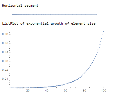
The following will create a horizontal mesh region of 100 elements where the initial element width is 1/10000 the domain length.
(*Create a graded horizontal mesh segment*)
(*Initial element width is 1/10000 the domain length*)
seg = leftSegmentGrowth[xmax, 100, xmax/10000];
Print["Horizontal segment"]
rh = pointsToMesh@seg
(*Convert mesh region to element mesh*)
(*Extract Coords from horizontal region*)
crd = MeshCoordinates[rh];
(*Create element mesh*)
mesh = ToElementMesh[crd];
Print["ListPlot of exponential growth of element size"]
ListPlot[Transpose@mesh["Coordinates"]]

One can see the exponential growth of the element size as the element number increases.
Convert the mesh region into an element mesh and solve the PDE
I generally convert the MeshRegion to an 'ElementMesh'so that I can apply element and point markers if needed.
(*Solve PDE on graded mesh*)
{Hfun, Pfun} =
  NDSolveValue[{eqsH, eqsP}, {H, P}, x ∈ mesh, {t, 0, tmax},
   Method -> {"MethodOfLines",
     "SpatialDiscretization" -> {"FiniteElement"}}];
(*Animate Hfun solution*)
imgs = Plot[Hfun[x, #], x ∈ mesh,
     PlotRange -> {0.9999999, 1.0018}] & /@ Subdivide[0, tmax, 120];
Print["Animation of Hfun solution"]
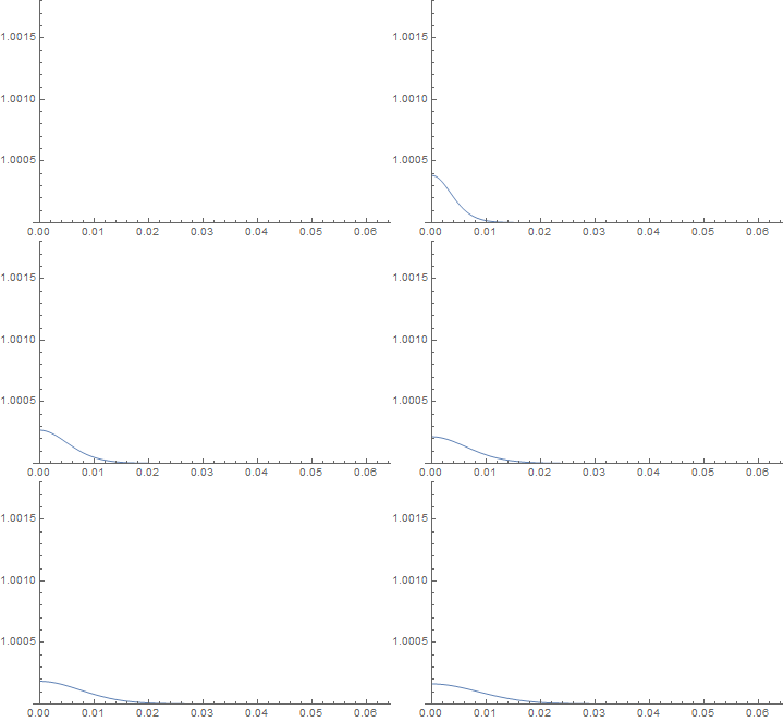
ListAnimate@imgs


