Tweeted twitter.com/StackMma/status/1266882183333109766
edited tags
Link
user21
  • 40.7k
  • 8
  • 114
  • 170
deleted 190 characters in body
Source Link

I am trying to solve the same PDE in Mathematica and MATLAB, Laplacian of phi = 0$\nabla^2\phi=0$ where phi is a function of x and y$\phi=f(x,y)$ It has a Dirichlet boundary condition on the left, a section of non-constant Neumann boundary condition on the right and zero flux everywhere else. The non-constant boundary condition is defined by enter image description here$\frac1{\sigma_i}\left(\frac{\sigma_i}{4e}\frac{\partial \mu}{\partial x}-I_e\right)$ where mu is a function of x and y$\mu=f(x,y)$ was previously solved for and all other variables are constants. I have developed code for to solve this PDE in both Mathematica and MATLAB however, they do not produce the same results, and I do not know which code is incorrect.

% Define constants
e = 1.60217662*10^-19;
sigi = 18;
F = 96485;
n = -0.02;
c = 1;
pO2 = 1.52*10^-19;
Ie = -(2*F)*(c*pO2^n);
mu2 = -5.98*10^-19;
l = 10*10^-6;
y1 = 0.01;
y2 = 0.0025;
y3 = 0.0075;

% Rectangle is code 3, 4 sides, followed by x-coordinates and then y-coordinates
R1 = [3,4,0,l,l,0,0,0,y2,y2]';
R2 = [3,4,0,l,l,0,y2,y2,y3,y3]';
R3 = [3,4,0,l,l,0,y3,y3,y1,y1]';
geom = [R1,R2,R3];
% Names for the two geometric objects
ns = (char('R1','R2','R3'))';
% Set formula
sf = 'R1+R2+R3';
% Create geometry
g = decsg(geom,sf,ns);

% Create mu geometry model
mumodel = createpde;
geometryFromEdges(mumodel,g);

% Apply boundary conditions
applyBoundaryCondition(mumodel,'dirichlet','Edge',8,'u',0);
applyBoundaryCondition(mumodel,'dirichlet','Edge',9,'u',0);
applyBoundaryCondition(mumodel,'dirichlet','Edge',10,'u',0);
applyBoundaryCondition(mumodel,'dirichlet','Edge',6,'u',mu2);
applyBoundaryCondition(mumodel,'neumann','Edge',1,'g',0);
applyBoundaryCondition(mumodel,'neumann','Edge',3,'g',0);
applyBoundaryCondition(mumodel,'neumann','Edge',4,'g',0);
applyBoundaryCondition(mumodel,'neumann','Edge',2,'g',0);
applyBoundaryCondition(mumodel,'neumann','Edge',5,'g',0);
applyBoundaryCondition(mumodel,'neumann','Edge',7,'g',0);

% Solve PDE for mu
specifyCoefficients(mumodel,'m',0,'d',0,'c',1,'a',0,'f',0);
generateMesh(mumodel,'Hmax',l);
solmu = solvepde(mumodel);

% Create phi geometry model
phimodel = createpde;
geometryFromEdges(phimodel,g);

% Make sure initial condition is suitable
setInitialConditions(phimodel,0);
setInitialConditions(phimodel,-0.7,'Edge',6);

% Define nonconstant Neumann boundary condition
bcfun = @(location,state)(sigi/(4*e)*evaluateGradient(solmu,l,location.y)-Ie)/sigi;

% Apply boundary conditions
applyBoundaryCondition(phimodel,'dirichlet','Edge',8,'u',0);
applyBoundaryCondition(phimodel,'dirichlet','Edge',9,'u',0);
applyBoundaryCondition(phimodel,'dirichlet','Edge',10,'u',0);
applyBoundaryCondition(phimodel,'neumann','Edge',6,'g',bcfun);
applyBoundaryCondition(phimodel,'neumann','Edge',1,'g',0);
applyBoundaryCondition(phimodel,'neumann','Edge',3,'g',0);
applyBoundaryCondition(phimodel,'neumann','Edge',4,'g',0);
applyBoundaryCondition(phimodel,'neumann','Edge',2,'g',0);
applyBoundaryCondition(phimodel,'neumann','Edge',5,'g',0);
applyBoundaryCondition(phimodel,'neumann','Edge',7,'g',0);

% Solve PDE for phi and plot results
specifyCoefficients(phimodel,'m',0,'d',0,'c',1,'a',0,'f',0);
generateMesh(phimodel,'Hmax',l);
solphi = solvepde(phimodel);
phi = solphi.NodalSolution;
pdeplot(phimodel,'XYData',phi)
title('Phi vs. x and y')
xlabel('x-position')
ylabel('y-position')

I am trying to solve the same PDE in Mathematica and MATLAB, Laplacian of phi = 0 where phi is a function of x and y It has a Dirichlet boundary condition on the left, a section of non-constant Neumann boundary condition on the right and zero flux everywhere else. The non-constant boundary condition is defined by enter image description here where mu is a function of x and y was previously solved for and all other variables are constants. I have developed code for to solve this PDE in both Mathematica and MATLAB however, they do not produce the same results, and I do not know which code is incorrect.

% Define constants
e = 1.60217662*10^-19;
sigi = 18;
F = 96485;
n = -0.02;
c = 1;
pO2 = 1.52*10^-19;
Ie = -(2*F)*(c*pO2^n);
mu2 = -5.98*10^-19;
l = 10*10^-6;
y1 = 0.01;
y2 = 0.0025;
y3 = 0.0075;

% Rectangle is code 3, 4 sides, followed by x-coordinates and then y-coordinates
R1 = [3,4,0,l,l,0,0,0,y2,y2]';
R2 = [3,4,0,l,l,0,y2,y2,y3,y3]';
R3 = [3,4,0,l,l,0,y3,y3,y1,y1]';
geom = [R1,R2,R3];
% Names for the two geometric objects
ns = (char('R1','R2','R3'))';
% Set formula
sf = 'R1+R2+R3';
% Create geometry
g = decsg(geom,sf,ns);

% Create mu geometry model
mumodel = createpde;
geometryFromEdges(mumodel,g);

% Apply boundary conditions
applyBoundaryCondition(mumodel,'dirichlet','Edge',8,'u',0);
applyBoundaryCondition(mumodel,'dirichlet','Edge',9,'u',0);
applyBoundaryCondition(mumodel,'dirichlet','Edge',10,'u',0);
applyBoundaryCondition(mumodel,'dirichlet','Edge',6,'u',mu2);
applyBoundaryCondition(mumodel,'neumann','Edge',1,'g',0);
applyBoundaryCondition(mumodel,'neumann','Edge',3,'g',0);
applyBoundaryCondition(mumodel,'neumann','Edge',4,'g',0);
applyBoundaryCondition(mumodel,'neumann','Edge',2,'g',0);
applyBoundaryCondition(mumodel,'neumann','Edge',5,'g',0);
applyBoundaryCondition(mumodel,'neumann','Edge',7,'g',0);

% Solve PDE for mu
specifyCoefficients(mumodel,'m',0,'d',0,'c',1,'a',0,'f',0);
generateMesh(mumodel,'Hmax',l);
solmu = solvepde(mumodel);

% Create phi geometry model
phimodel = createpde;
geometryFromEdges(phimodel,g);

% Make sure initial condition is suitable
setInitialConditions(phimodel,0);
setInitialConditions(phimodel,-0.7,'Edge',6);

% Define nonconstant Neumann boundary condition
bcfun = @(location,state)(sigi/(4*e)*evaluateGradient(solmu,l,location.y)-Ie)/sigi;

% Apply boundary conditions
applyBoundaryCondition(phimodel,'dirichlet','Edge',8,'u',0);
applyBoundaryCondition(phimodel,'dirichlet','Edge',9,'u',0);
applyBoundaryCondition(phimodel,'dirichlet','Edge',10,'u',0);
applyBoundaryCondition(phimodel,'neumann','Edge',6,'g',bcfun);
applyBoundaryCondition(phimodel,'neumann','Edge',1,'g',0);
applyBoundaryCondition(phimodel,'neumann','Edge',3,'g',0);
applyBoundaryCondition(phimodel,'neumann','Edge',4,'g',0);
applyBoundaryCondition(phimodel,'neumann','Edge',2,'g',0);
applyBoundaryCondition(phimodel,'neumann','Edge',5,'g',0);
applyBoundaryCondition(phimodel,'neumann','Edge',7,'g',0);

% Solve PDE for phi and plot results
specifyCoefficients(phimodel,'m',0,'d',0,'c',1,'a',0,'f',0);
generateMesh(phimodel,'Hmax',l);
solphi = solvepde(phimodel);
phi = solphi.NodalSolution;
pdeplot(phimodel,'XYData',phi)
title('Phi vs. x and y')
xlabel('x-position')
ylabel('y-position')
I am trying to solve the same PDE in Mathematica and MATLAB, $\nabla^2\phi=0$ where $\phi=f(x,y)$ It has a Dirichlet boundary condition on the left, a section of non-constant Neumann boundary condition on the right and zero flux everywhere else. The non-constant boundary condition is defined by $\frac1{\sigma_i}\left(\frac{\sigma_i}{4e}\frac{\partial \mu}{\partial x}-I_e\right)$ where $\mu=f(x,y)$ was previously solved for and all other variables are constants. I have developed code for to solve this PDE in both Mathematica and MATLAB however, they do not produce the same results, and I do not know which code is incorrect.

% Define constants
e = 1.60217662*10^-19;
sigi = 18;
F = 96485;
n = -0.02;
c = 1;
pO2 = 1.52*10^-19;
Ie = -(2*F)*(c*pO2^n);
mu2 = -5.98*10^-19;
l = 10*10^-6;
y1 = 0.01;
y2 = 0.0025;
y3 = 0.0075;

% Rectangle is code 3, 4 sides, followed by x-coordinates and then y-coordinates
R1 = [3,4,0,l,l,0,0,0,y2,y2]';
R2 = [3,4,0,l,l,0,y2,y2,y3,y3]';
R3 = [3,4,0,l,l,0,y3,y3,y1,y1]';
geom = [R1,R2,R3];
% Names for the two geometric objects
ns = (char('R1','R2','R3'))';
% Set formula
sf = 'R1+R2+R3';
% Create geometry
g = decsg(geom,sf,ns);

% Create mu geometry model
mumodel = createpde;
geometryFromEdges(mumodel,g);

% Apply boundary conditions
applyBoundaryCondition(mumodel,'dirichlet','Edge',8,'u',0);
applyBoundaryCondition(mumodel,'dirichlet','Edge',9,'u',0);
applyBoundaryCondition(mumodel,'dirichlet','Edge',10,'u',0);
applyBoundaryCondition(mumodel,'dirichlet','Edge',6,'u',mu2);
applyBoundaryCondition(mumodel,'neumann','Edge',1,'g',0);
applyBoundaryCondition(mumodel,'neumann','Edge',3,'g',0);
applyBoundaryCondition(mumodel,'neumann','Edge',4,'g',0);
applyBoundaryCondition(mumodel,'neumann','Edge',2,'g',0);
applyBoundaryCondition(mumodel,'neumann','Edge',5,'g',0);
applyBoundaryCondition(mumodel,'neumann','Edge',7,'g',0);

% Solve PDE for mu
specifyCoefficients(mumodel,'m',0,'d',0,'c',1,'a',0,'f',0);
generateMesh(mumodel,'Hmax',l);
solmu = solvepde(mumodel);

% Create phi geometry model
phimodel = createpde;
geometryFromEdges(phimodel,g);

% Make sure initial condition is suitable
setInitialConditions(phimodel,0);
setInitialConditions(phimodel,-0.7,'Edge',6);

% Define nonconstant Neumann boundary condition
bcfun = @(location,state)(sigi/(4*e)*evaluateGradient(solmu,l,location.y)-Ie)/sigi;

% Apply boundary conditions
applyBoundaryCondition(phimodel,'dirichlet','Edge',8,'u',0);
applyBoundaryCondition(phimodel,'dirichlet','Edge',9,'u',0);
applyBoundaryCondition(phimodel,'dirichlet','Edge',10,'u',0);
applyBoundaryCondition(phimodel,'neumann','Edge',6,'g',bcfun);
applyBoundaryCondition(phimodel,'neumann','Edge',1,'g',0);
applyBoundaryCondition(phimodel,'neumann','Edge',3,'g',0);
applyBoundaryCondition(phimodel,'neumann','Edge',4,'g',0);
applyBoundaryCondition(phimodel,'neumann','Edge',2,'g',0);
applyBoundaryCondition(phimodel,'neumann','Edge',5,'g',0);
applyBoundaryCondition(phimodel,'neumann','Edge',7,'g',0);

% Solve PDE for phi and plot results
specifyCoefficients(phimodel,'m',0,'d',0,'c',1,'a',0,'f',0);
generateMesh(phimodel,'Hmax',l);
solphi = solvepde(phimodel);
phi = solphi.NodalSolution;
pdeplot(phimodel,'XYData',phi)
title('Phi vs. x and y')
xlabel('x-position')
ylabel('y-position')
Source Link
kjcole
  • 353
  • 1
  • 5

Mathematica vs. MATLAB: why am I getting different results for PDE with non-constant boundary condition?

I am trying to solve the same PDE in Mathematica and MATLAB, Laplacian of phi = 0 where phi is a function of x and y It has a Dirichlet boundary condition on the left, a section of non-constant Neumann boundary condition on the right and zero flux everywhere else. The non-constant boundary condition is defined by enter image description here where mu is a function of x and y was previously solved for and all other variables are constants. I have developed code for to solve this PDE in both Mathematica and MATLAB however, they do not produce the same results, and I do not know which code is incorrect.

Below is the full Mathematica code:

Needs["NDSolve`FEM`"]
e = 1.60217662*10^-19;
sigi = 18; 
F = 96485; 
n = -0.02; 
c = 1;
pO2 = 1.52*10^-19;
Ie = -(2*F)*(c*pO2^n);
mu2 = -5.98*10^-19;
l = 10*10^-6;
y1 = 0.01;
y2 = 0.0025;
y3 = 0.0075;
meshRefine[vertices_, area_] := area > 10^-12;
mesh = ToElementMesh[
   DiscretizeRegion[ImplicitRegion[True, {{x, 0, l}, {y, 0, y1}}]], 
   MeshRefinementFunction -> meshRefine];
bcmu = {DirichletCondition[mu[x, y] == 0, (x == 0 && 0 < y < y1)], 
  DirichletCondition[
   mu[x, y] == 
    mu2, (x == l && 
     y2 < y < y3)]};
solmu = NDSolve[{Laplacian[mu[x, y], {x, y}] == 
    0 + NeumannValue[0, 
      y == 0 || 
       y == y1 || (x == l && 0 <= y <= y2) || (x == l && 
         y3 <= y <= y1)], bcmu}, 
  mu, {x, y} \[Element] mesh];
bcphi = DirichletCondition[phi[x, y] == 0, (x == 0 && 0 < y < y1)];
A = (Ie - sigi/(4*e)*(D[mu[x, y] /. solmu, x] /. x -> l))/(-sigi);
solphi = NDSolve[{Laplacian[phi[x, y], {x, y}] == 
     0 + NeumannValue[0, 
       y == 0 || 
        y == y1 || (x == l && 0 <= y <= y1) || (x == l && 
          y3 <= y <= y1)] + 
      NeumannValue[-A[[1]], x == l && y2 < y < y3], bcphi}, 
   phi, {x, y} \[Element] mesh];
DensityPlot[phi[x, y] /. solphi, {x, 0, l}, {y, 0, y1}, 
 PlotLabel -> "Phi vs. x and y", PlotLegends -> Automatic]

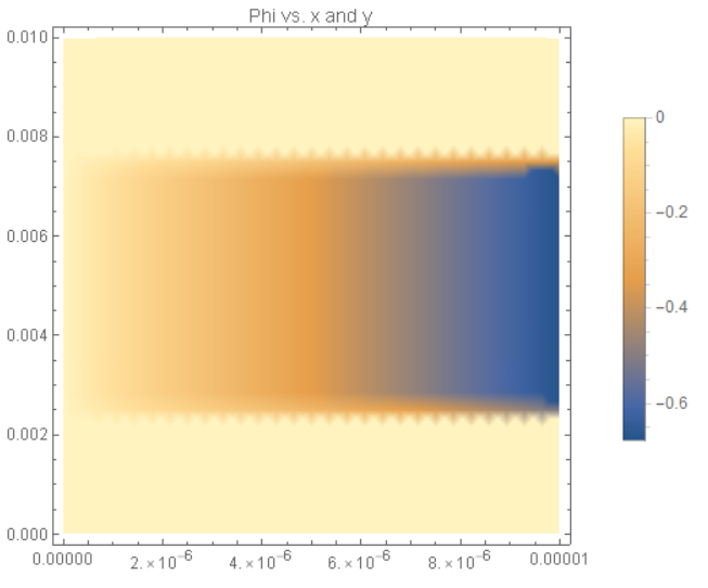
The code produces this result for phi:

Mathematica result

And here is the MATLAB code:

% Define constants
e = 1.60217662*10^-19;
sigi = 18;
F = 96485;
n = -0.02;
c = 1;
pO2 = 1.52*10^-19;
Ie = -(2*F)*(c*pO2^n);
mu2 = -5.98*10^-19;
l = 10*10^-6;
y1 = 0.01;
y2 = 0.0025;
y3 = 0.0075;

% Rectangle is code 3, 4 sides, followed by x-coordinates and then y-coordinates
R1 = [3,4,0,l,l,0,0,0,y2,y2]';
R2 = [3,4,0,l,l,0,y2,y2,y3,y3]';
R3 = [3,4,0,l,l,0,y3,y3,y1,y1]';
geom = [R1,R2,R3];
% Names for the two geometric objects
ns = (char('R1','R2','R3'))';
% Set formula
sf = 'R1+R2+R3';
% Create geometry
g = decsg(geom,sf,ns);

% Create mu geometry model
mumodel = createpde;
geometryFromEdges(mumodel,g);

% Apply boundary conditions
applyBoundaryCondition(mumodel,'dirichlet','Edge',8,'u',0);
applyBoundaryCondition(mumodel,'dirichlet','Edge',9,'u',0);
applyBoundaryCondition(mumodel,'dirichlet','Edge',10,'u',0);
applyBoundaryCondition(mumodel,'dirichlet','Edge',6,'u',mu2);
applyBoundaryCondition(mumodel,'neumann','Edge',1,'g',0);
applyBoundaryCondition(mumodel,'neumann','Edge',3,'g',0);
applyBoundaryCondition(mumodel,'neumann','Edge',4,'g',0);
applyBoundaryCondition(mumodel,'neumann','Edge',2,'g',0);
applyBoundaryCondition(mumodel,'neumann','Edge',5,'g',0);
applyBoundaryCondition(mumodel,'neumann','Edge',7,'g',0);

% Solve PDE for mu
specifyCoefficients(mumodel,'m',0,'d',0,'c',1,'a',0,'f',0);
generateMesh(mumodel,'Hmax',l);
solmu = solvepde(mumodel);

% Create phi geometry model
phimodel = createpde;
geometryFromEdges(phimodel,g);

% Make sure initial condition is suitable
setInitialConditions(phimodel,0);
setInitialConditions(phimodel,-0.7,'Edge',6);

% Define nonconstant Neumann boundary condition
bcfun = @(location,state)(sigi/(4*e)*evaluateGradient(solmu,l,location.y)-Ie)/sigi;

% Apply boundary conditions
applyBoundaryCondition(phimodel,'dirichlet','Edge',8,'u',0);
applyBoundaryCondition(phimodel,'dirichlet','Edge',9,'u',0);
applyBoundaryCondition(phimodel,'dirichlet','Edge',10,'u',0);
applyBoundaryCondition(phimodel,'neumann','Edge',6,'g',bcfun);
applyBoundaryCondition(phimodel,'neumann','Edge',1,'g',0);
applyBoundaryCondition(phimodel,'neumann','Edge',3,'g',0);
applyBoundaryCondition(phimodel,'neumann','Edge',4,'g',0);
applyBoundaryCondition(phimodel,'neumann','Edge',2,'g',0);
applyBoundaryCondition(phimodel,'neumann','Edge',5,'g',0);
applyBoundaryCondition(phimodel,'neumann','Edge',7,'g',0);

% Solve PDE for phi and plot results
specifyCoefficients(phimodel,'m',0,'d',0,'c',1,'a',0,'f',0);
generateMesh(phimodel,'Hmax',l);
solphi = solvepde(phimodel);
phi = solphi.NodalSolution;
pdeplot(phimodel,'XYData',phi)
title('Phi vs. x and y')
xlabel('x-position')
ylabel('y-position')

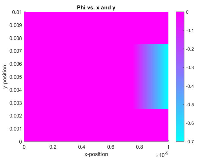
The MATLAB code produces this as the results for phi: MATLAB result

Which code is correct? Where is the error?