Prelude
Mathematica 11.3, Windows.
Let us say I have a rectangular region with 10 little holes inside. Their coordinates are given by positionList. The resulting region mr is made through RegionDifference and RegionUnion of disks and rectangles:
Needs["NDSolve`FEM`"]

radius = 0.1;
Louter = 2;
OuterRegion = Rectangle[{-L/2, -L/2}, {L/2, L/2}] /. L -> Louter;

positionList = {{0.706`, -0.14`}, {0.389`, 0.593`}, {-0.278`,
    0.429`}, {0.254`,
    0.844`}, {-0.46`, -0.367`}, {0.737`, -0.759`}, {-0.07`, -0.664`}, \
{-0.469`, 0.626`}, {-0.755`, -0.509`}, {-0.455`, -0.015`}};
diskRegions = Disk[#, radius] & /@ positionList;
mr = RegionDifference[OuterRegion, RegionUnion@diskRegions];

LP = ListPlot[positionList -> Table[k, {k, 1, Length@positionList}]];
RP = Show[mr // RegionPlot, LP, ImageSize -> 400]
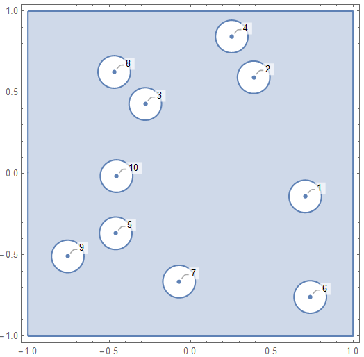
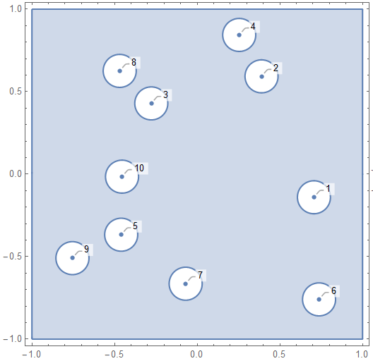
The labels of the disks show the order in which they appear in positionList. Ultimately I want a FEM mesh where I can apply specific boundary conditions on disk 1, disk 2, disk 3 etc. First, I make a boundary mesh:
bmesh = ToBoundaryMesh[RegionBoundary@mr,
   "RegionHoles" -> positionList, "BoundaryGroupingThreshold" -> 0,
   AccuracyGoal -> 1];
Show[bmesh["Wireframe"["MeshElementMarkerStyle" -> Blue]],
 ImageSize -> 400]
Problem
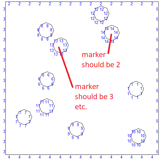
As you can see, the Region Markers are scrambled! In the boundary mesh, the hole corresponding to disk 2 (in the blue plot above) actually has marker 14. Hole 3 has marker 13, and so on.
I want the markers of the boundary mesh to be consistent with the disk numbers, here going from 1 to 10. The markers on the walls should have numbers 11-14.
A manual solution
I have solved this problem with a BoundaryMarkerFunction, writing a condition manually for each disk and each of the walls:
boundaryMarkerFunction =
  Compile[{{boundaryElementCoords, _Real,
     3}, {pointMarkres, _Integer, 2}},
   Module[{pt1 = #[[1]], pt2 = #[[2]]},
      Which[

       (pt1[[1]] - positionList[[1]][[1]])^2 + (pt1[[2]] -
            positionList[[1]][[2]])^2 <
         1.1 radius^2 && (pt2[[1]] -
            positionList[[1]][[1]])^2 + (pt2[[2]] -
            positionList[[1]][[2]])^2 < 1.1 radius^2 , 1,
       (pt1[[1]] - positionList[[2]][[1]])^2 + (pt1[[2]] -
            positionList[[2]][[2]])^2 <
         1.1 radius^2 && (pt2[[1]] -
            positionList[[2]][[1]])^2 + (pt2[[2]] -
            positionList[[2]][[2]])^2 < 1.1 radius^2 , 2,
       (pt1[[1]] - positionList[[3]][[1]])^2 + (pt1[[2]] -
            positionList[[3]][[2]])^2 <
         1.1 radius^2 && (pt2[[1]] -
            positionList[[3]][[1]])^2 + (pt2[[2]] -
            positionList[[3]][[2]])^2 < 1.1 radius^2 , 3,
       (pt1[[1]] - positionList[[4]][[1]])^2 + (pt1[[2]] -
            positionList[[4]][[2]])^2 <
         1.1 radius^2 && (pt2[[1]] -
            positionList[[4]][[1]])^2 + (pt2[[2]] -
            positionList[[4]][[2]])^2 < 1.1 radius^2 , 4,
       (pt1[[1]] - positionList[[5]][[1]])^2 + (pt1[[2]] -
            positionList[[5]][[2]])^2 <
         1.1 radius^2 && (pt2[[1]] -
            positionList[[5]][[1]])^2 + (pt2[[2]] -
            positionList[[5]][[2]])^2 < 1.1 radius^2 , 5,
       (pt1[[1]] - positionList[[6]][[1]])^2 + (pt1[[2]] -
            positionList[[6]][[2]])^2 <
         1.1 radius^2 && (pt2[[1]] -
            positionList[[6]][[1]])^2 + (pt2[[2]] -
            positionList[[6]][[2]])^2 < 1.1 radius^2 , 6,
       (pt1[[1]] - positionList[[7]][[1]])^2 + (pt1[[2]] -
            positionList[[7]][[2]])^2 <
         1.1 radius^2 && (pt2[[1]] -
            positionList[[7]][[1]])^2 + (pt2[[2]] -
            positionList[[7]][[2]])^2 < 1.1 radius^2 , 7,
       (pt1[[1]] - positionList[[8]][[1]])^2 + (pt1[[2]] -
            positionList[[8]][[2]])^2 <
         1.1 radius^2 && (pt2[[1]] -
            positionList[[8]][[1]])^2 + (pt2[[2]] -
            positionList[[8]][[2]])^2 < 1.1 radius^2 , 8,
       (pt1[[1]] - positionList[[9]][[1]])^2 + (pt1[[2]] -
            positionList[[9]][[2]])^2 <
         1.1 radius^2 && (pt2[[1]] -
            positionList[[9]][[1]])^2 + (pt2[[2]] -
            positionList[[9]][[2]])^2 < 1.1 radius^2 , 9,
       (pt1[[1]] - positionList[[10]][[1]])^2 + (pt1[[2]] -
            positionList[[10]][[2]])^2 <
         1.1 radius^2 && (pt2[[1]] -
            positionList[[10]][[1]])^2 + (pt2[[2]] -
            positionList[[10]][[2]])^2 < 1.1 radius^2 , 10,
       pt1[[1]] < -0.99 && pt2[[1]] < -0.99, 11, (* left wall *)
       pt1[[2]] < -0.99 && pt2[[2]] < -0.99, 12, (* bottom wall *)
       pt1[[1]] > 0.99 && pt2[[1]] > 0.99, 13, (* right wall *)
       pt1[[2]] > 0.99 && pt2[[2]] > 0.99, 14, (* top wall *)

       True, 4 ]] & /@ boundaryElementCoords];

bmesh = ToBoundaryMesh[RegionBoundary@mr,
   "RegionHoles" -> positionList, "BoundaryGroupingThreshold" -> 0,
   AccuracyGoal -> 2,
   "BoundaryMarkerFunction" -> boundaryMarkerFunction];
{Show[bmesh["Wireframe"["MeshElementMarkerStyle" -> Blue]],
  ImageSize -> 400], RP}
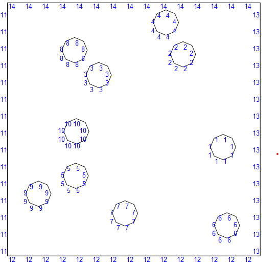
An automatic solution?
Could this be automated, so I can vary the number of disks? I would have happily replaced the Which construct by some Table, but I am not sure what kind of arguments this mysterious boundaryMarkerFunction takes. For instance, I tried
boundaryMarkerFunction[bmesh["BoundaryElements"],
 bmesh["Coordinates"]]
which fails because boundaryElementCoords is supposed to be 3D.
Please help me find an automatic solution to label the boundary elements in my desired order.
Just for fun
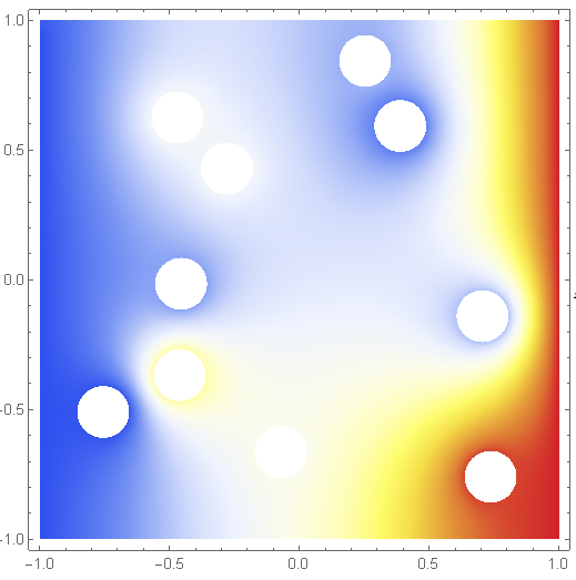
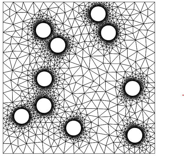
This allows us to use ElementMarker with NDSolve, specifying precise individual boundary conditions on the disks. For instance, here is the heat equation with a different DirichletCondition on each disk:
bmesh = ToBoundaryMesh[RegionBoundary@mr,
   "RegionHoles" -> positionList, "BoundaryGroupingThreshold" -> 0,
   AccuracyGoal -> 4,
   "BoundaryMarkerFunction" -> boundaryMarkerFunction];
mesh = ToElementMesh[bmesh];

boundaryMarkerList = Table[k, {k, 1, Length@positionList}];

op = - Laplacian[u[x, y], {x, y}] + 0.1 u[x, y];
BCedges = {DirichletCondition[u[x, y] == 0, ElementMarker == 11],
   DirichletCondition[u[x, y] == 1, ElementMarker == 13]};
BCcircles =
  Table[DirichletCondition[u[x, y] == RandomReal[{0, 1}],
    ElementMarker == k], {k, 1, Length@positionList}];
BC = Join[BCedges, BCcircles];
ufun = NDSolveValue[{op == 0, BC}, u, {x, y} \[Element] mesh]

{
 DensityPlot[ufun[x, y], {x, y} \[Element] mesh,
  ColorFunction -> "Temperature", AspectRatio -> Automatic,
  PlotPoints -> 100, PlotRange -> All, ImageSize -> 400],
 Show[mesh["Wireframe"], ImageSize -> 400]
 }
