42
$\begingroup$

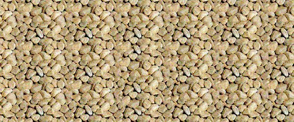
Given a background and a pattern jpg files, is there a quick and easy way to produce a stereogram by using Mathematica? The following picture was produced from Photoshop, spent about half an hour. enter image description here

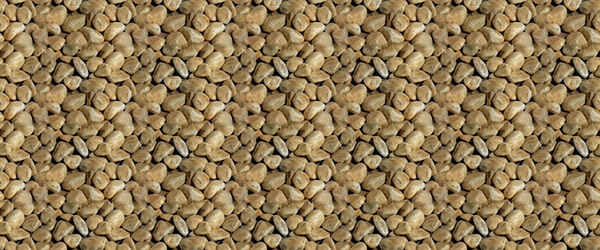
Here is the background tile for creating the blank background below:

enter image description here

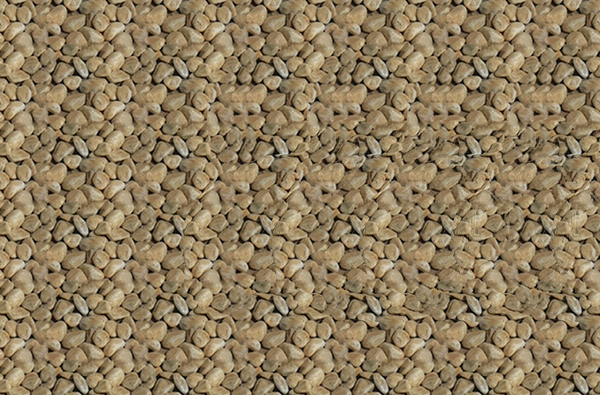
and here is a blank background picture of pebbles: enter image description here

$\endgroup$
6
  • 1
    $\begingroup$ Could you supply the sample background and .jpg image, along with information about or link to "stereogram"? $\endgroup$
    – John McGee
    Commented Aug 9, 2014 at 14:52
  • 1
    $\begingroup$ What is the hidden image? I can never see them. $\endgroup$
    – shrx
    Commented Aug 9, 2014 at 18:00
  • $\begingroup$ This demonstration may be a good place to start. How did you do it in Photoshop? $\endgroup$ Commented Aug 9, 2014 at 18:10
  • $\begingroup$ Is the hidden image of a person's head? $\endgroup$ Commented Aug 9, 2014 at 19:42
  • 2
    $\begingroup$ Related: R. Maeder, TMJ (1995) 1. $\endgroup$
    – Michael E2
    Commented Aug 10, 2014 at 2:54

5 Answers 5

38
$\begingroup$

Here's an alternative method which takes a depth map.

This is a complete change from my original code - my apologies for doing such a major edit after receiving so many upvotes but it was not quite right before (there were artifacts in the 3D view). This version is based on the description here.

I upsample the pattern image and depth map before creating the stereogram, and afterwards downsample the result back to the correct size. This is to allow a greater number of depth planes without having to explicitly interpolate to get sub-pixel shifts.

For better performance I use a compiled function to do the actual pixel-copying core of the algorithm. I have used compilation to C but for those without a C compiler it will work just as well (but a bit slower) using the WVM.

The final function stereogram takes as arguments the pattern image, the depth image and the desired number of tiles in width and height. The fourth optional argument is the maximum pixel shift in the upsampled image - this is also the number of distinct depth planes.

shift = Compile[{
    {im, _Real, 3}, {d, _Integer, 2}, {nx2, _Integer},
    {ny, _Integer}, {w, _Integer}, {h, _Integer}},
   Block[{i = im}, Do[i[[y, x + d[[y, x]]]] = i[[y, x - d[[y, x]]]],
     {y, h ny}, {x, 1 + nx2, 2 w nx2 - nx2}]; i],
   CompilationTarget -> "C"];

sg[pattern_, depthmap_, copies_, maxshift_] :=
 Module[{nx, ny, p, w, h, i, d},
  {nx, ny} = ImageDimensions[pattern];
  p = If[OddQ[nx], ImageCrop[pattern, {nx = nx - 1, ny}], pattern];
  {w, h} = copies;
  i = ImageData @ ImageAssemble@ConstantArray[p, {h, w}];
  d = depthmap ~ImageCrop~ {w nx, h ny} ~ColorConvert~ "Grayscale";
  d = Round[nx/2 - maxshift Clip[ImageData @ d, {0, 1}]];
  Image[shift[i, d, nx/2, ny, w, h]]]

stereogram[pattern_Image, depthmap_Image, copies_List: {5, 5}, maxshift_: 40] :=
 sg[pattern ~ImageResize~ Scaled[5],
   depthmap ~ImageResize~ Scaled[5],
   copies, maxshift] ~ImageResize~ Scaled[1/5]

Example:

pattern = Import["https://i.sstatic.net/nQKct.jpg"];
depthmap = Import["https://i.sstatic.net/RJf51.png"];

stereogram[pattern, depthmap, {6, 5}]

enter image description here

$\endgroup$
6
  • $\begingroup$ Very nice, it pops! $\endgroup$ Commented Aug 10, 2014 at 19:56
  • $\begingroup$ Cool, I tried to follow your method to get depth map for the 'bunny = ExampleData[{"Geometry3D", "StanfordBunny"}, "VertexData"]' like:'deptmap = ListSurfacePlot3D[bunny, MaxPlotPoints -> 50, Mesh -> None, Boxed -> False, Axes -> None, Ticks -> None, PlotStyle -> Directive[Specularity[White, 5] ], Lighting -> "Neutral"] ', the outcome was not satisfactory. How to get a dept map from a 3D model? $\endgroup$
    – Putterboy
    Commented Aug 10, 2014 at 21:36
  • 1
    $\begingroup$ @user16069, it should be fairly easy to create a depth map from a 3D model. You just need to shade each vertex according to its distance from the viewpoint. If you need help with it I would suggest asking a new question. $\endgroup$ Commented Aug 13, 2014 at 14:49
  • $\begingroup$ For those of us not yet on V10, could you post a version without RadialGradientImage. I tried using depth = ImageCrop[ ImageAdjust@ Rasterize[ DensityPlot[Cos[x] + Cos[y], {x, 0, 4 Pi}, {y, 0, 4 Pi}, ColorFunction -> GrayLevel, Frame -> False], ImageSize -> {w nx, h ny}], {w nx, h ny}], But all I'm getting are Thread::tdlen: Objects of unequal length in, when running the shift part. (Still +1:) $\endgroup$
    – Ajasja
    Commented Aug 13, 2014 at 18:50
  • $\begingroup$ I guess something like ImageAdjust@ Rasterize@ DensityPlot[(Sqrt[x^2 + y^2]) ( Cos[6 (Sqrt[x^2 + y^2])] - 0.5), {x, -3, 3}, {y, -3, 3}, Frame -> None, ColorFunction -> GrayLevel, PlotRange -> All] Could work instead of RadialGradientImage $\endgroup$
    – Ajasja
    Commented Aug 13, 2014 at 19:21
14
$\begingroup$

Here is something to play with. The method comes from the tutorial. The gui uses ImageMultiply and SetAlphaChannel to copy a piece of the background defined by object. Then it uses ImagePerspectiveTransformation and TranslationTransform to move the copy to a new position. Finally ImageCompose is used to paste the copied section at the new position on the original background. The tutorial mentioned a second copy to eliminate an artifact, so I threw in a second copy to see the effect.

(* get a texture *)
texture = Import["https://i.sstatic.net/nQKct.jpg"];
tdims = ImageDimensions@texture;

(* add some noise *)
texture = ImageEffect[texture, {"GaussianNoise", 0.1}];

(* tile the noisy texture *)
background = ImagePad[texture, {{0, 5*First@tdims}, {0, 2*Last@tdims}}, "Periodic"];
bdims = ImageDimensions@background;

(* create an object to hide *)
object = ImageCrop@Image@Graphics[{Rectangle[{0, 0}, bdims], White, 
 Disk[bdims/2 - {First@bdims/6, 0}, 0.45*First@tdims]},ImageSize -> bdims]

Manipulate[
  ImageCompose[
  ImageCompose[
   background, 
   ImagePerspectiveTransformation[#, TranslationTransform[{shift, 0}]]],
   ImagePerspectiveTransformation[#, TranslationTransform[{shift - x, 0}]]] &@
   SetAlphaChannel[ImageMultiply[background, #], #] &@object, 
{shift,0, 1}, {x, 0, 1}]

Autostereogram manipulate

Edit: Don't forget the bonus decoder

Manipulate[
 ImageDifference[#, 
    ImagePerspectiveTransformation[#,TranslationTransform[{t, 0}]]
 ] &@autoStereogramImage,
{t,0,1}]
$\endgroup$
5
  • $\begingroup$ Great, but I get lost about your last edit, what is autoSterogramImage for. And is it possible to create more than a single layer for the stereo image? $\endgroup$
    – Putterboy
    Commented Aug 10, 2014 at 2:58
  • $\begingroup$ autostereogram is any Magic-Eye or similar image, like the image in my answer. By playing with the slider, the Bonus decoder will reveal the hidden object without requiring you to do crazy eye tricks. You can get more than a single layer, and a multiple hidden objects as well. Just copy other sections of the picture and shift them by different amounts. $\endgroup$ Commented Aug 10, 2014 at 3:14
  • $\begingroup$ If we can add more layers, can't we add a 3d image/plot? $\endgroup$
    – P. Fonseca
    Commented Aug 10, 2014 at 8:28
  • 1
    $\begingroup$ @P.Fonseca, I started with that idea, but first you need to take a 3D plot, convert it to a depth image, and then convert the smooth depths to a small set of layers, kind of like converting a sphere into a ball of Lego blocks. I think converting a 3D plot to a depth image warrants its own question here on SE. $\endgroup$ Commented Aug 10, 2014 at 12:45
  • $\begingroup$ The question about creating a depth image has been asked and collectively answered. $\endgroup$ Commented Jul 26, 2015 at 19:03
4
$\begingroup$

Here is an alternative for making a stereogram:

Download and import a 3D object file into Mathematica, which is something looks like this:

enter image description here

Assuming that the extracted .obj file located on the root of your C: drive, Load and make a pose of the rabbit in Mathematica:

Clear[vpdata, vvdata, vpdata2, vvdata2, vpD, vvD];
rabbit = Import["c:\\rabbit.obj" ];
f[a_] := (Show[rabbit, Background -> Black,
   ViewPoint -> a[[1]],
   ViewVertical -> a[[2]],
   ImageSize -> {70, 70}] )

vpdata = {-3.0, 0.3 , 1.6};
vvdata = {-1.2 , 0.9, 0.3 };
vpdata2 = {-2.4 , 0.1, 2.4};
vvdata2 = {-1.1, 0.9, 0.4};
vpD = vpdata2 - vpdata;
vvD = vvdata2 - vvdata;

making a list of total 9 slightly different posing rabbits:

imgNo = 8;
vpFin = Table[{{
     vpdata[[1]] + vpD[[1]]*t/imgNo,
     vpdata[[2]] + vpD[[2]]*t/imgNo,
     vpdata[[3]] + vpD[[3]]*t/imgNo},
    {vvdata[[1]] + vvD[[1]]*t/imgNo,
     vvdata[[2]] + vvD[[2]]*t/imgNo,
     vvdata[[3]] + vvD[[3]]*t/imgNo} }, {t, 0, imgNo }];

imArr = ImageResize[#, {70, 70}] & /@ f /@ vpFin;

combing the tiles into strips:

bgband = Graphics[ {}, Background -> Black, ImageSize -> {70*(imgNo + 1), 70}] ;
background = 
  Graphics[ {}, Background -> Black, ImageSize -> {70*(imgNo + 1), 5*70}] ;
For[i = 1, i <= 9, i++,
    bgband2 = ImageCompose[ bgband, imArr[[i]], {35 + (i - 1)*70, 35}];
   bgband = bgband2;
  ];
For[i = 1, i <= 9, i++,
    bgband3 = ImageCompose[ bgband, imArr[[5]], {35 + (i - 1)*70, 35}];
   bgband = bgband3;
  ];

produce the stereogram:

bground = ImageCompose[background, bgband3, {315, 35}];
bground = ImageCompose[bground, bgband3, {315, 105}];
bground = ImageCompose[bground, bgband2, {315, 175}] ;
bground = ImageCompose[bground, bgband3, {315, 245}];
bground = ImageCompose[bground, bgband3, {315, 315}] 

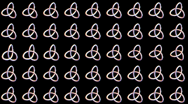
enter image description here

Note the rabbits in the third row. And the following picture was produced by the same method:

enter image description here

$\endgroup$
1
  • 3
    $\begingroup$ You can get a built in bunny with ExampleData[{"Geometry3D", "StanfordBunny"}]. $\endgroup$
    – Greg Hurst
    Commented Aug 13, 2014 at 15:26
4
$\begingroup$

I couldn't help my self, so here is a 3D (V9 compliant) bunny:) (Some artifacts, perhaps of pixels being shifted too much are still present...)

pattern = Import["https://i.sstatic.net/nQKct.jpg"];
{nx, ny} = ImageDimensions[pattern];
pt = Flatten[ImageData[pattern], 1];
data = ExampleData[{"Geometry3D", "StanfordBunny"}, "VertexData"];

{w, h} = {8, 8};(*how many copies of the pattern*)
y = Join @@ Table[ConstantArray[nx Mod[i, ny], w nx], {i, 0, h ny - 1}];
x = Range[w h nx ny];

depth = ColorConvert[
  ImageCrop[
   Rasterize[
    ListSurfacePlot3D[data, MaxPlotPoints -> 50, 
     ColorFunction -> (Glow[GrayLevel[#3]] &), Mesh -> None, 
     Background -> Black, Boxed -> False, ViewPoint -> {0, 0, 10}, 
     Axes -> False], ImageSize -> Round[{w nx, h ny}*0.6]], {w nx, 
    h ny}], "Grayscale"]

shift = Round[
   6 Flatten[Accumulate[Partition[#, nx]] & /@ ImageData@depth]];
Image[Partition[pt[[y + Mod[x + shift, nx, 1]]], w nx]]

3D bunny

$\endgroup$
2
  • $\begingroup$ Regarding the artifacts, I think I may have the algorithm slightly wrong, though I can't see where. When I get a chance I will try to fix it. $\endgroup$ Commented Aug 14, 2014 at 8:28
  • $\begingroup$ @SimonWoods Yes, I had to reduce the scaling factor before flatten to get better results (but less depth). Reducing the size of the bunny also helped. $\endgroup$
    – Ajasja
    Commented Aug 14, 2014 at 9:52
1
$\begingroup$

A bit too late to the party, I found that there's no way to add texture to the rabbit using @Simon's method, thus I created one of my own. Effect first!
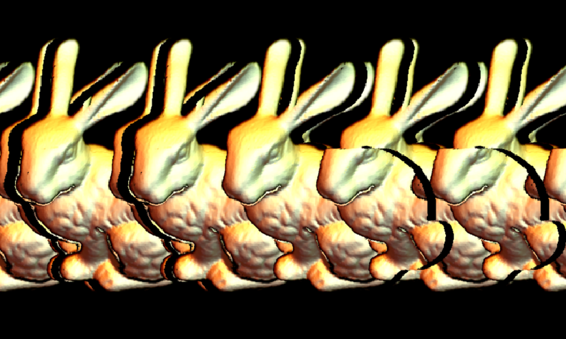
sample

One rabbit only, correct texture for the rabbit for most part.

The code is as follows, and could be downloaded here:

mappedstereogram[img_Image, depth_Image, bg_Image, n_List: {5, 3}, 
  shift_: 40, supersampling_: 2, filter_: 1] :=
 Module[{imgbg, imgmap, imgdep, 
   dimo = Round[ImageDimensions[bg]*supersampling, 2], l, conn},
  imgbg = 
   ImageData@
    ImageAssemble@
     ConstantArray[
      ImageResize[ColorConvert[bg, "RGB"], dimo, 
       Resampling -> "Linear"], Reverse@n];
  imgmap = 
   ImageData@
    ImageCrop[
     ImageResize[ColorConvert[img, "RGB"], Scaled@supersampling, 
      Resampling -> "Linear"], n dimo];
  imgdep = 
   Round[dimo[[1]]/2 - 
     shift Clip[
       ImageData@
        ImageCrop[
         ImageResize[ColorConvert[depth, "Grayscale"], 
          Scaled@supersampling, Resampling -> "Linear"], n dimo], {0, 
        1}]];

  l = Length@imgdep[[1]];

  Table[
   conn = 
    ConnectedComponents@
     Graph@Select[
       Flatten[MapIndexed[{(l + #2[[1]]) <-> (#2[[1]] - #1), (l + #2[[
               1]]) <-> (#2[[1]] + #1)} &, imgdep[[i]]], 1], 
       0 < #[[2]] <= l &];

   MapThread[
    With[{res = 
        Select[Thread@{#1, imgmap[[i, #1]]}, Max@#[[2]] != 0. &]}, 
      imgbg[[i, #2]] = 
       ConstantArray[
        If[Length@res != 0., SortBy[res, #[[1]] &][[1, 2]], 
         imgbg[[i, #2[[1]]]]], Length@#2]] &, {Pick[conn, 
       UnitStep[l - conn], 0] - l, Pick[conn, UnitStep[l - conn], 1]}]

   , {i, Floor[(Length@imgbg - 
        supersampling ImageDimensions[depth][[2]])/2], 
    Ceiling[(Length@imgbg + 
        supersampling ImageDimensions[depth][[2]])/2]}];

  ImageResize[MedianFilter[Image@imgbg, filter], 
   Scaled[1/supersampling], Resampling -> "Linear"]
  ]

input are a texture image img, a corresponding depth image depth, and a background image bg.

First three lines of code are responsible for formatting the image to the same scale. Then we start to create the stereogram using the following equation:

$$f(x,y,h(x,y))=g(x-\alpha h(x,y),y)=g(x+\alpha h(x,y),y)$$

where $f$ and $g$ are pixel value on the object and on the image plane, $\alpha$ is the difference of viewing angle of two eyes, and $h(x,y)$ are the depth of the image.

We first find out the correlation between $f$ and $g$ by constructing a graph and calculate its connected components. A connected component like $f(x_0)\leftrightarrow g(x_1)\leftrightarrow f(x_2)\leftrightarrow g(x_3), f(x_2)\leftrightarrow g(x_4)$ means these positions should share the same pixel value!

Then by using the texture given by $f(x_0)$ to render $g(x_1), g(x_3),g(x_4)$, we can have the correct stereogram.

To avoid defects, super sampling and MedianFilter are implemented.

This method can be used together with @Simons' to get augment visual effects:
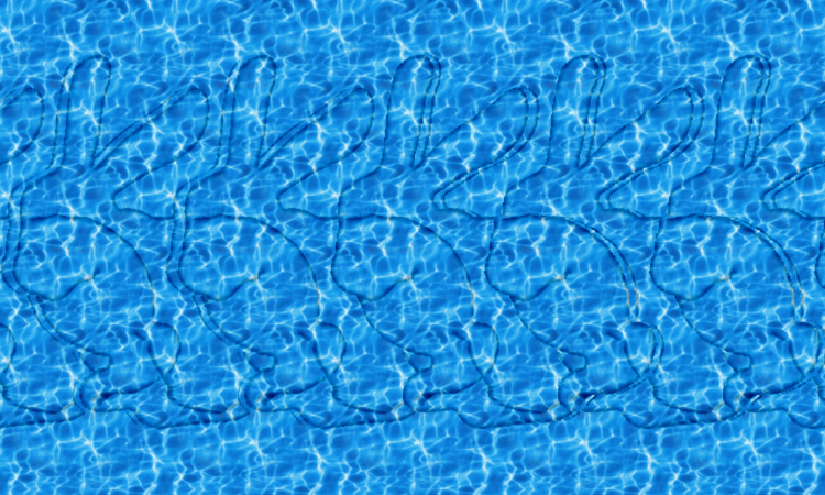
augment

$\endgroup$

Your Answer

By clicking “Post Your Answer”, you agree to our terms of service and acknowledge you have read our privacy policy.

Not the answer you're looking for? Browse other questions tagged or ask your own question.